Is DTC status displayed as Present?

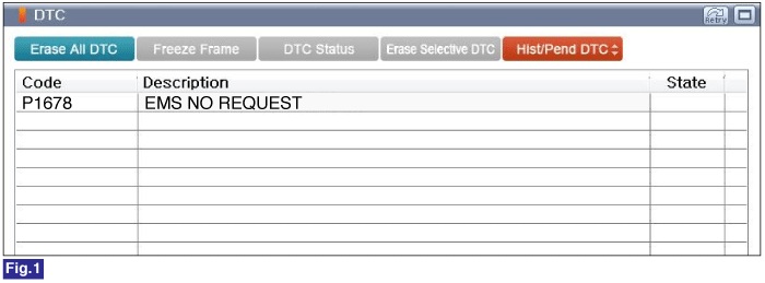
Fig 1) Diagnostic Trouble Code(DTC) is shown above
 | ▶ Go to "Monitor GDS Data" procedure. |
 | ▶ Go to "Verification of Vehicle Repair" procedure. |
Connect GDS to Data Link Connector(DLC).
Ignition "ON"
Monitor "Diagnostic Trouble Codes(DTC)" with GDS.
Is DTC status displayed as Present?

Fig 1) Diagnostic Trouble Code(DTC) is shown above
 | ▶ Go to "Monitor GDS Data" procedure. |
 | ▶ Go to "Verification of Vehicle Repair" procedure. |
Ignition "OFF"
Connect GDS and setup the oscilloscope.
Back probe and measure signal waveform of Pin No. 2 (Coil (+)) terminal of antenna coil(+) and chassis ground with VMI.
Back probe and measure signal waveform of Pin No. 1 (Coil (-))terminal of antenna coil(-) and chassis ground with VMI.
Ignition "ON" , Engine "OFF"
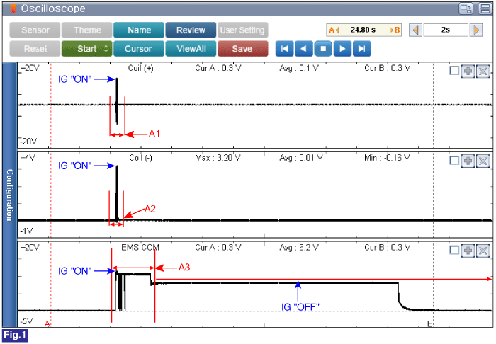
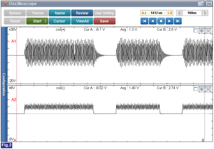
Specification : Refer to Figure below


Fig 1) Normal Waveforms of Key Box Coil(+,-) & EMS COM at Ignition "OFF" -> "ON"
Fig 2) Normal Waveforms of Key Box Coil(+,-) "OFF" -> "ON" (Time Frame : 100 micor-sec.)
Is the measured signal waveform normal?
 | ▶ Fault is intermittent caused by poor contact in Immobilizer Control Unit and/or PCM's connector or was repaired and Immobilizer Control Unit and memory was not cleared. Thoroughly check connectors for looseness, poor connection, bending, corrosion, contamination, deterioration, or damage. Repair or replace as necessary and then go to "Verification of Vehicle Repair" procedure. |
 | ▶ Go to "Check EMS communication" procedure. |
Ignition "ON" & Engine "OFF"
Connect GDS and setup the oscilloscope.
Back probe and measure signal waveform of Pin No. 61 (EMS) terminal of PCM harness connector and chassis ground by using VMI A channel. (AT)
Back probe and measure signal waveform of Pin No. 83 (EMS) terminal of PCM harness connector and chassis ground by using VMI A channel. (MT)
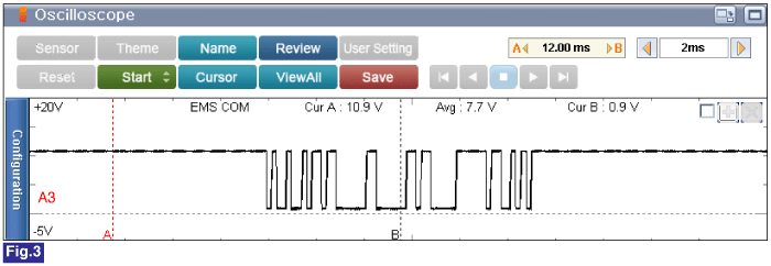
Specification : Refer to Figure below

Fig 3) Normal Waveforms of EMS COM at Ignition "OFF" -> "ON" (Time Frame : 2 msec.)
Is the measured signal waveform normal?
 | ▶ Fault is intermittent caused by poor contact in Immobilizer Control Unit and/or PCM's connector or was repaired and Immobilizer Control Unit and memory was not cleared. Thoroughly check connectors for looseness, poor connection, bending, corrosion, contamination, deterioration, or damage. Repair or replace as necessary and then go to "Verification of Vehicle Repair" procedure. |
 | ▶ Go to "Component inspection" procedure. |