Check for resistance and output voltage between terminals in each switch position.
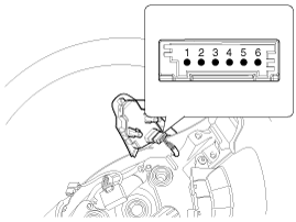
Switch | Connector terminal | Resistance (±5%) | Output voltage (V) |
Cancel | 2-4 | 180 Ω | 0.63 ~ 0.97 |
Set | 2-4 | 330 Ω | 1.03 ~ 1.37 |
Resume | 2-4 | 550 Ω | 1.58 ~2.02 |
Cruise | 2-4 | 880 Ω | 2.08 ~2.52 |
Speed limit | 2-4 | 2.54 kΩ | 3.38 ~ 3.82 |
If the measured resistance is not within specification, replace the switch and measure the voltage again.
If the measured voltage is not within the specification, inspect the control switch resistance.
If the measured resistance is OK, but the measured voltage is not within the specification, inspect the wiring harness and connectors between the switch and ECM.
Disconnect the negative (-) battery terminal.
Remove the driver airbag module.
(Refer to Restraint - "Driver Airbag (DAB) Module and Clock Spring")
Remove the steering wheel.
(Refer to Steering System - "Steering Column and Shaft")
Loosen the mounting screws from the rear steering wheel cover.
Separate the upper steering wheel remote control switch (A) from the steering wheel.
Remove the upper steering wheel control switch (B) disconnecting the connector (A).
Reassemble the cruise control switch after connecting the connector.
Reassemble the driver airbag module.
Make sure the audio remote control switch and the airbag module connectors are plugged in properly.