2.
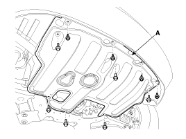
Remove the engine room under cover (A).
Common Rail Fuel Injection System operates with extremely high pressure (approximately 1,600bar), so never perform any work on injection system with engine running or within 30 seconds after the engine stops.
Keep cleanly the parts and the working area.
Pay attention to a foreign substance.
Just before installing injector, tube or hose, remove the protect-cap attached on them.
Do not remove injector except for special case.
When installing Injector
- Wash the contact area of the injector and replace the O-ring with a new one. - Spread oil on the injector O-ring. - To protect damage caused by shock, vertically insert the injector into the cylinder head. |
When installing High Pressure Fuel Pipe
- Do not use again the used high pressure fuel pipe. - Install the flange nut correctly. |
Turn ignition switch OFF and disconnect the battery negative (-) battery terminal.
Remove the engine room under cover (A).
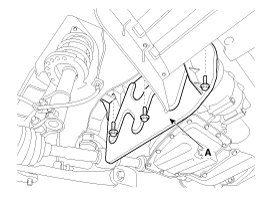
Remove the engine room side cover RH (A).
Remove the drive belt.
(Refer to Engine Mechanical System - "Drive Belt")
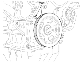
Turn the crankshaft pulley and align its groove with timing mark "T" of the timing chain cover.(NO.1 cylinder compression TDC position.)
Remove the starter.
(Refer to Engine Electrical System - "Starter" )
Install the fixing flywheel stopper (A) [SST No: 09231-2B100] on the flywheel.
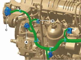
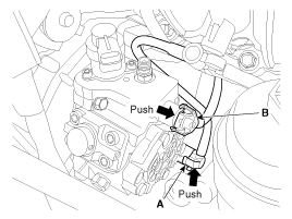
Disconnect the fuel pressure control valve connector (A), fuel temperature sensor connector (B) and variable Swirl actuator (C).
Remove the oil level gauge & guide.
(Refer to Engine Mechanical System - "Oil Level Gauge & Pipe")
Remove the wiring harness (A) after loosening the mounting bolt.
Remove the high pressure fuel pipe flange nut (B) after loosening the clamp mounting bolt (A).
High pressure fuel pipe clamp mounting blot:
6.8 ~ 10.7 N.m (0.7 ~ 1.1 kgf.m, 5.1 ~ 8.0 lb-ft)
High pressure fuel pipe flange nut:
24.5 ~ 28.4 N.m (2.5 ~ 2.9 kgf.m, 18.1 ~ 21.0 lb-ft)
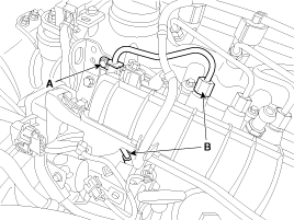
Remove the low fuel line bracket (B) after loosening the mounting bolt (A).
Disconnect the fuel feed tube quick connector (A) and the fuel return tube quick connector from the high pressure fuel pump by pushing the lock pins in the direction of the arrows.
Lift the RH side of the engine with a jack (A).
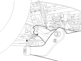
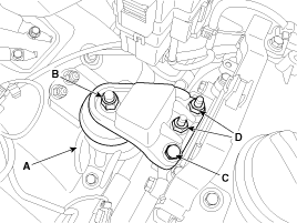
Remove the engine support bracket (A).
Engine support bracket mounting bolt/nut:
Nut (B) : 78.5 ~ 98.1 N.m (8.0 ~ 10.0 kgf.m, 57.9 ~ 72.3 lb-ft)
Bolt (C), Nuts (D) : 58.8 ~ 73.5 N.m (6.0 ~ 7.5 kgf.m, 43.4 ~ 54.2 lb-ft)
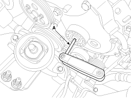
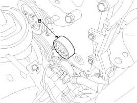
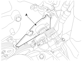
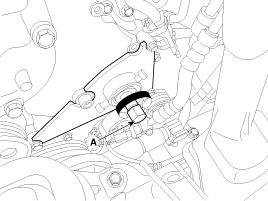
Remove the idler (B) using the wrench (A).
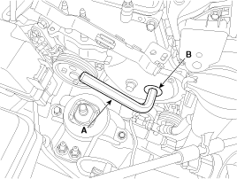
Remove the timing chain cover plug (B) using the wrench (A).
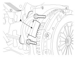
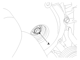
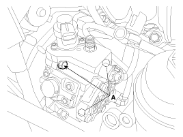
Remove the high pressure fuel pump sprocket nut (A).
High pressure fuel pump sprocket nut:
64.7 ~ 74.5 N.m (8.0 ~ 10.0 kgf.m, 47.7 ~ 55.0 lb-ft)
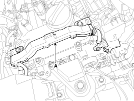
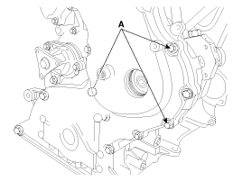
Remove the timing chain cover mounting bolts (A).
Fix the high pressure fuel pump remover and stopper (A) [SST No.: 09331-2A010] after lift the RH side of the engine with a jack.
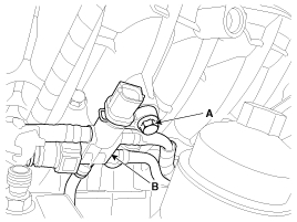
Remove the high pressure fuel pump mounting bolts (A).
High fuel pump mounting bolt:
19.6 ~ 25.5 N.m (2.0 ~ 2.6 kgf.m, 14.5 ~ 18.8 lb-ft)
If it is difficult to remove the high pressure fuel pump mounting bolts using a socket wrench with a thick head, you can use a 1/4” 12mm socket as shown below.
[Arrangement of tools for removing high pressure fuel pump]
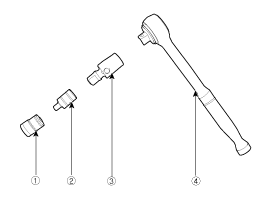
① 1/4" 12mm socket
② 1/4" to 3/8" drive socket adapter (only if using 1/4" drive socket)
③ 3/8" universal joint
④ Socket wrench
Install the high pressure fuel pump mounting bolt (A) [SST No.: 09331-2A010]
Rotate the bolt (A) of the high pressure fuel pump remover [SST No.:09331-2A010] clockwise till the high pressure fuel pump is pushed out.
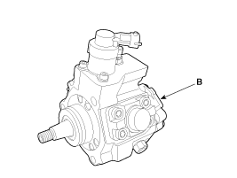
Remove the high pressure fuel pump (B).
Install in the reverse order of removal.
When installing the high pressure fuel pipes, apply the specified tightening torques with the special service tools (Refer to the below table).
Item | Dimension | Tool Name |
Flange Nut (HP Pump Side) | 14 mm | 09314-27110 |
Flange Nut (CommonRail Side) | 17 mm | 09314-27120 |
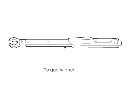
If it is difficult to use the special service tools 09314-27110 or 09314-27120 for tightening some of the high pressure fuel pipe flange nuts to the specified torque, you can use a spanner torque wrench as shown below.
After removing or replacing the part below, bleed air in low pressure fuel circuit.
(Refer to Fuel Delivery System - "Bleeding Air in Low Pressure Fuel Circuit")
Fuel Tank
Fuel Sender
Fuel Filter
High Pressure Fuel Pump
Low Pressure Fuel Lines
