Has a problem been found?
 | ▶ Repair as necessary and go to "Verification of Vehicle Repair" procedure. |
 | ▶ Go to "Squib Circuit Inspection" procedure. |
Many malfunctions in the electrical system are caused by poor connection. Faults can also be caused by interference from other electrical systems, and mechanical or chemical damage.
Thoroughly check connectors for looseness, poor connection, bending, corrosion, contamination, deterioration,or damage.
Has a problem been found?
 | ▶ Repair as necessary and go to "Verification of Vehicle Repair" procedure. |
 | ▶ Go to "Squib Circuit Inspection" procedure. |
Ignition "OFF".
Disconnect (-) terminal cable from battery and wait for 1 minutes or more.
Remove the DAB module and connect the dummy and dummy adapter to DAB connector of the clock spring harness connector.
If dummy and dummy adaptor are not able to be prepared, use a known-good DAB or 2Ω resistor.
Lay removed DAB facing upward for unexpected air bag deploy.
Connect (-) terminal cable to battery and Ignition "ON" & Engine "OFF" and wait for 30 seconds or more.
Connect GDS to Data Link Connector(DLC) and clear DTC with GDS and diagnose again.
Is any DTC present?
 | ▶ Go to "Clock Spring Circuit Inspection" procedure. |
 | ▶ If no problems were found with the circuits or connectors, Replace the DAB(Driver Airbag) and go to "Verification of Vehicle Repair" procedure. |
Ignition switch "OFF".
Disconnect the battery (-) terminal cable from the battery and wait at least one minutes.
Remove DAB module and disconnect SRSCM connector of the clock spring harness.
Lay removed DAB facing upward for unexpected air bag deploy.
Measure resistance between terminal pin No.2(High) of clock spring harness connector and chassis ground.
Measure resistance between terminal pin No.1(Low) of clock spring harness connector and chassis ground.
Specification : ∞ (Infinite)Ω

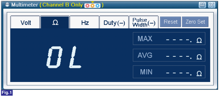
Fig.1) GDS Multimeter resistance check
Are the measured value within specification?
 | ▶ Go to "Main Circuit Inspection" procedure. |
 | ▶ If no problems were found with the circuits or connectors, Replace the clock spring and go to "Verification of Vehicle Repair" procedure. |
Ignition switch "OFF".
Disconnect the battery (-) terminal cable from the battery and wait at least one minutes.
Remove DAB module and disconnect SRSCM connector and the clock spring connector.
Lay removed DAB facing upward for unexpected air bag deploy.
Measure resistance between terminal pin No.2(High) of DAB connector and chassis ground.
Measure resistance between terminal pin No.1(Low) of DAB connector and chassis ground.
Specification : ∞ (Infinite)Ω

Fig.1) GDS Multimeter resistance check
Are the measured value within specification?
 | ▶ If no problems were found with the circuits or connectors, Replace the SRSCM and go to "Verification of Vehicle Repair" procedure. |
 | ▶ If no problems were found with the circuits or connectors, Replace the SRSCM main circuit and go to "Verification of Vehicle Repair" procedure. |