IG KEY "OFF".
Connnect CH A probe to FR signal terminal (Pin No.3) of Alternator connector and CH B probe to COM signal terminal (Pin No.1) of Alternator connector.
Warm up the engine to normal operating temperature.
Measure signal waveform of FR and COM.
Specification : Refer to Signal Waveform & Data
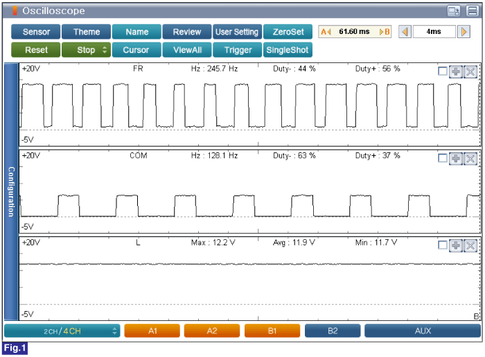
Fig.1) Engine Idle after Warm Up
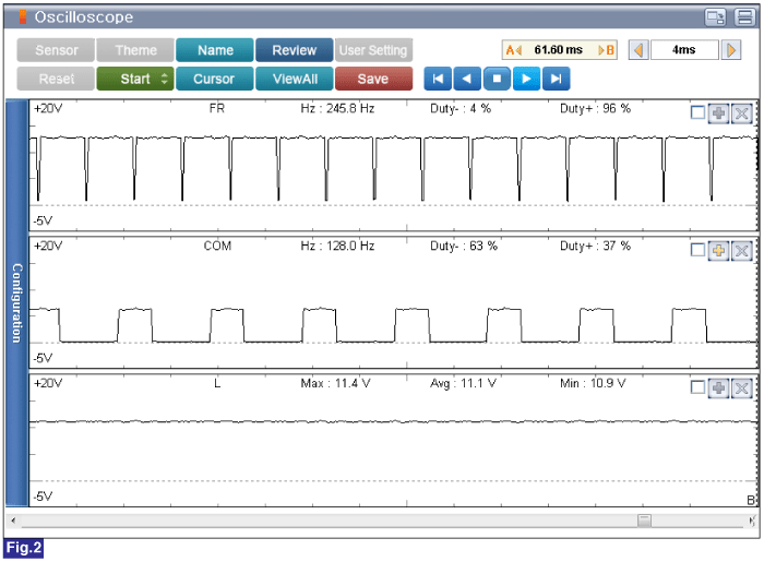
Fig.2) Electrical Load(Engine Idle after Warm Up)
Duty(+) from FR terminal is increased if electrical loads are ON(Head Lamp and Defrost are ON) ECM/PCM controls generation of alternator with duty from FR terminal when electrical Loads turn on.
Does the Alternator operate properly? (Check variation)
![]() | ▶ Go to "Verification of Vehicle Repair" procedure. |
![]() | ▶ Carefully re-do this troubleshooting guide steps. ▶ If problem still occurs, replace Alternator and then go to "Verification of Vechicle Repair" procedure. |