EEGR Acturator | Terminal | Inspection Condition | Measured Value | Remarks | |
Pin No. | 1 | EGR Feedback Signal | 1. Ignition Switch "ON", Engine "OFF" 2. Measure Voltage of Wiring Side(Disconnected) | Approx. 5V | - |
2 | EGR Feecback Ground | Approx. 0V | - | ||
3 | EGR Feedback Power | Approx. 4.1V | - | ||
4 | EGR Actuator Power | B+ | - | ||
5 | - | - | - | ||
6 | EGR Actuator Control | Approx. 3.6V | - | ||
EEGR Acturator | Terminal | Inspection Condition | Measured Value | Remarks | |
Pin No. | 1 | EGR Feedback Signal | 1. Ignition Switch "ON", Engine "OFF" 2. Measure Voltage of Wiring Side(Connected) | Approx. 5V | - |
2 | EGR Feecback Ground | Approx. 0V | - | ||
3 | EGR Feedback Power | Approx. 1.0V | - | ||
4 | EGR Actuator Power | B+ | - | ||
5 | - | - | - | ||
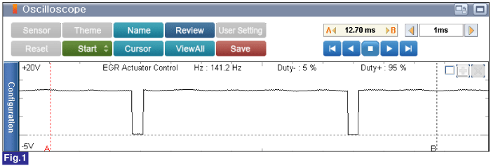
6 | EGR Actuator Control | Average Approx. 11.5V | Duty(Fig. 1) | ||

Fig.1 ) IG "ON" & Engine "OFF", EGR actuator control output is 5% duty. The purpose of this control is that to check the EEGR circuit.