Inspection condition : Engine Idle
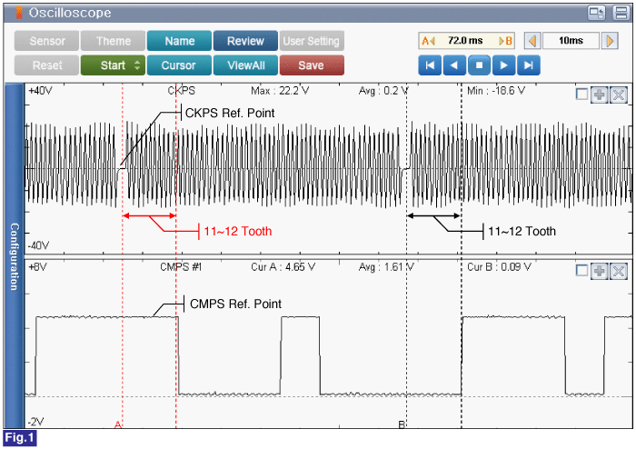
Specification : Refer to Fig. below

Fig.1 ) At idle, CKPS & CMPS Signal Waveform. The ECM determines the firing order with Low and High signal of the CKPS Ref. point and the CMPS Ref. point.
Ignition Switch "OFF"
Connect VMI to GDS and select oscilloscope.(2 Channel)
Channel A (+) : Pin No. 2(Signal High) connector (On CKPS Connector)
Channel A (-) : Pin No. 1(Signal Low) connector (On CKPS Connector)
Channel B (+) : Pin No. 2(CMPS Signal) connector (On CMPS Connector)
Channel B (-) : Ground
IG "ON" / Engine "ON"
Inspection condition : Engine Idle
Specification : Refer to Fig. below
Ignition Switch "OFF"
Connect VMI to GDS and select oscilloscope.(2 Channel)
Channel A (+) : Pin No. 3(Signal High) connector (On CKPS Connector)
Channel A (-) : Pin No. 2(Signal Low) connector (On CKPS Connector)
Channel B (+) : Pin No. 2(CMPS Signal) connector (On CMPS Connector)
Channel B (-) : Ground
IG "ON" / Engine "ON"
Inspection condition : Engine Idle
Specification : Refer to Fig. below

Fig.1 ) At idle, CKPS & CMPS Signal Waveform. The ECM determines the firing order with Low and High signal of the CKPS Ref. point and the CMPS Ref. point.
Is the measured value within specification?
 | ▶ Fault is intermittent caused by poor contact in the sensor’s and/or ECM’s connector or was repaired and ECM memory was not cleared. Thoroughly check connectors for looseness, poor connection, bending, corrosion, contamination, deterioration, or damage. Repair or replace as necessary and go to "Verification of vehicle Repair" procedure. |
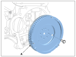
 | ▶ Refer to "Shop Manual" and check distortion on the fly wheel. ▶ If the fly wheel is ok, go to "Resistance Inspection" procedure. |

Ignition Switch "OFF"
Disconnect battery (-) cable.
Refer to "Shop Manual" and disconnect the CKPS connector.
Measure resistance between Pin No. 2(High) and Pin No. 3(Low) of the CKPS.
Specification : Approx. 860Ω(20℃)
Ignition Switch "OFF"
Disconnect battery (-) cable.
Refer to "Shop Manual" and disconnect the CKPS connector.
Measure resistance between Pin No. 2(Low) and Pin No. 3(High) of the CKPS.
Specification : Approx. 860Ω(20℃)
Is the measured value within specification?
 | ▶ Fault is intermittent caused by poor contact in the sensor’s and/or ECM’s connector or was repaired and ECM memory was not cleared. Thoroughly check connectors for looseness, poor connection, bending, corrosion, contamination, deterioration, or damage. Repair or replace as necessary and go to "Verification of vehicle Repair" procedure. |
 | ▶ If no problems were found with the circuits or connectors, Replace the CKPS unit and go to "Verification of Vehicle Repair" procedure. warning
•
When install a part, tighten it within specification.
•
When drop down the part, check part's operating condition whether it is damaged or not. |