Perform "Actuation Test" for Injector.
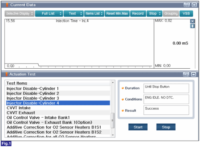
Fig.1) Injector Disable - Cylinder 4 Actuation Test
Connect GDS to Data Link Connector(DLC).
IG KEY "ON" & ENG "OFF".
Perform "Actuation Test" for Injector.

Fig.1) Injector Disable - Cylinder 4 Actuation Test
IG KEY "OFF".
Connect VMI to GDS and select "Oscilloscope".
Connect Channel A positive probe to Pin No.2 (High side) and Channel A negative probe to Pin No.1 (Low side).
Connnect CH AUX probe to control wire of Injector.
Warm up the engine to normal operating temperature.
Specification : Refer to Signal Waveform & Data
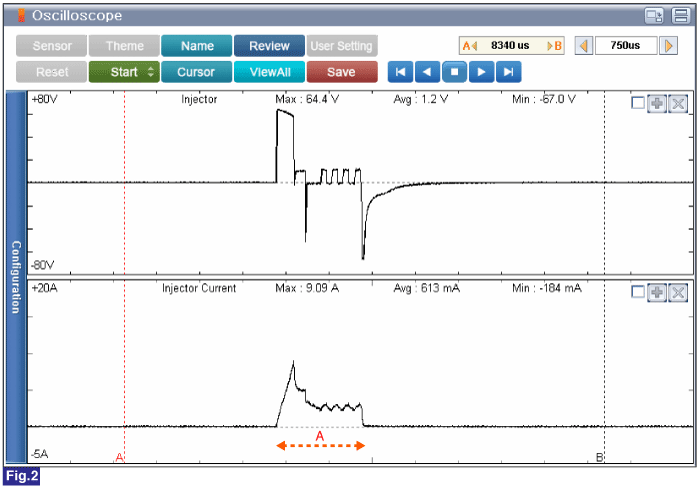
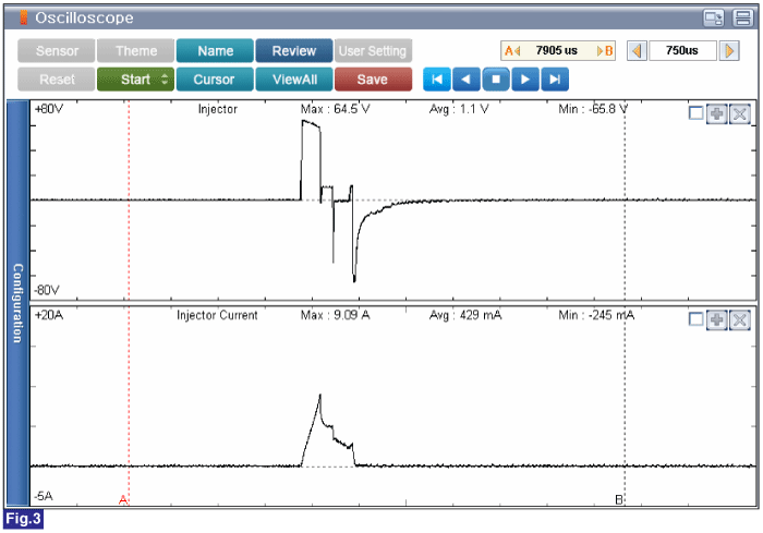
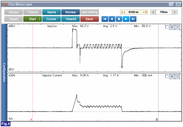
Fig.2) Engine Idle after Warm Up
A: Fuel injection time - Approx. 1450us
CH. A - Injector Max 64.5V
CH. AUX - Injector Current MAX 9.21A
Fig.3) Approx. 2500rpm
A: Fuel injection time - Approx. 900us
CH. A - Injector Max 64.9V
CH. AUX - Injector Current MAX 9.15A
Fig.4) At Acceleration
CH. A - Injector Max 65.2V
CH. AUX - Injector Current MAX 9.09A
IG Key "OFF".
Disconnect Injector connector.
Measure resistance between Pin No.2(High side) terminal and Pin No.1(Low side) terminal of the Injector. (Component Side)
Specification : Approx. 1.40 Ω [25°C(77°F)]
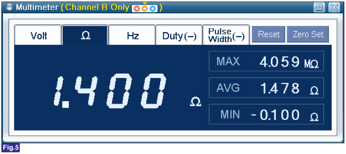
Fig.5) Resistance of Injector
Does the Injector operate properly? (Check variation)
 | ▶ Go to "Verification of Vehicle Repair" procedure. |
 | ▶ Carefully re-do this troubleshooting guide steps. ▶ If problem still occurs, replace Injector and then go to "System Inspection" procedure. |