Remove the cylinder head cover.
(Refer to Cylinder Head Assembly - "Cylinder Head Cover")
Set the piston of No.1 cylinder to the TDC (top dead center) on compression stroke.
Turn the crankshaft pulley clockwise and align its groove with the timing mark of the timing chain cover.
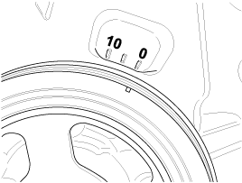
Do not rotate engine counterclockwise.
Check that the TDC marks of the intake CVVT sprocket and exhaust camshaft sprocket are in straight line on the cylinder head surface as shown in the illustration.
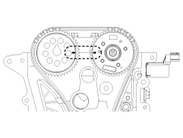
If not, turn the crankshaft one revolution (360°). (Do not rotate engine counterclockwise.)
Mark on the timing chain links corresponding to the timing marks of the intake CVVT sprocket and exhaust camshaft sprocket.
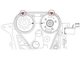
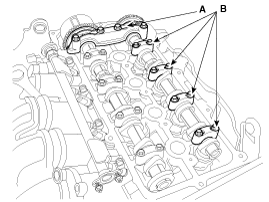
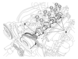
Remove the front camshaft bearing cap (A) and the exhaust camshaft bearing caps (B).
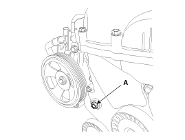
Remove the service hole bolt (A) on the timing chain cover.
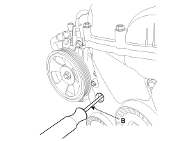
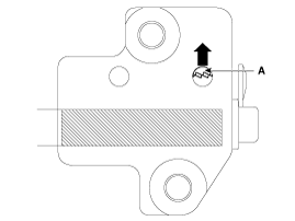
Release the ratchet (A) of the timing chain tensioner by pushing and holding the ratchet upward using a thin rod (B).
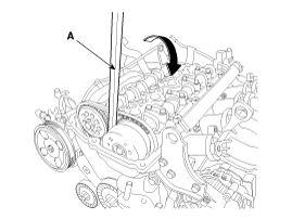
Loosen the timing chain by pushing the tensioner arm using a handy bar (A).
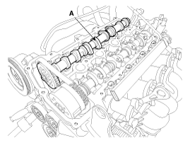
Remove the exhaust camshaft (A).
Remove the intake camshaft bearings (A) then remove the intake camshaft (B).
To hold the timing chain, tie it with strap.
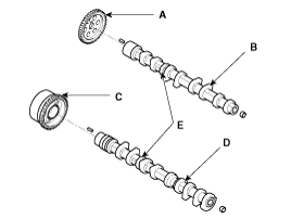
Disassemble the sprocket (A) from the exhaust camshaft (B) and the CVVT assembly (C) from the intake camshaft (D).
When removing the CVVT assembly and camshaft sprocket bolts, hold the camshaft at designated point (E) using a wrench to prevent the camshaft from rotating.
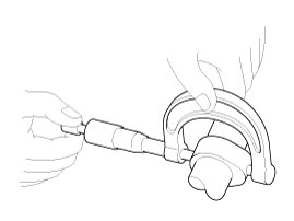
Inspect the cam height.
Using a micrometer, measure the cam height.
Cam height
Intake : 43.85 mm (1.7264 in)
Exhaust : 42.85 mm (1.6870 in)
If the cam lobe height is less than specified, replace the camshaft.
Inspect the camshaft journal clearance.
Clean the bearing caps and camshaft journals.
Place the camshafts on the cylinder head.
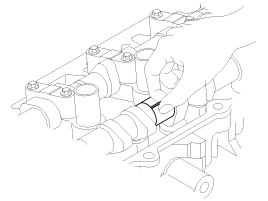
Lay a strip of plastigage across each of the camshaft journal.
Install the bearing caps and tighten the bolts with specified torque.
Tightening torque
M6 bolts :
11.8 ~ 13.7 N.m (1.2 ~ 1.4 kgf.m, 8.7 ~ 10.1 lb-ft)
M8 bolts :
18.6 ~ 22.6 N.m (1.9 ~ 2.3 kgf.m, 13.7 ~ 16.6 lb-ft)
Do not turn the camshaft.
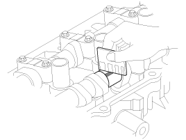
Remove the bearing caps.
Measure the plastigage at its widest point.
Bearing oil clearance
Standard :
0.027 ~ 0.058 mm (0.0011 ~ 0.0023 in)
Limit : 0.1 mm ( 0.0039 in)
If the oil clearance is greater than specification, replace the camshaft.
If the oil clearance is still greater than specification after camshaft replacement, replace the bearing caps and cylinder head as a set.
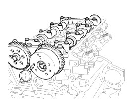
Inspect the camshaft end play.
Install the camshafts.
Using a dial indicator, measure the end play while moving the camshaft back and forth.
Camshaft end play :
0.1 ~ 0.2 mm (0.0039 ~ 0.0079 in)
If the end play is greater than specification, replace the camshaft.
If the end play is still greater than specification after camshaft replacement, replace the bearing caps and cylinder head as a set.
Remove the camshafts.
Inspect the CVVT assembly.
Fix the CVVT assembly with its camshaft in a vice.
Check that the CVVT assembly will not turn. If it is not turned, it is in normal condition.
Apply vinyl tape to all the parts except the one hole.
Using an air gun, apply the pressure, 147.10 kPa (1.5 kg/cm², 21.33 psi) in the hole.
This makes the lock pin in maximum retarded state released.
Wrap around it with a shop rag and the likes, because the oil splashes.
After releasing the pin, you can turn the CVVT assembly for advance by hand.
If there was too much air leakage, the pin can not be released
Under the condition of 3), turn the CVVT assembly to the advance angle side with your hand.
Depending on the air pressure, the CVVT assembly will turn to the advance side.
Also, under the condition that the pressure can be hardly applied because of the air leakage from the port, there may be the case that the lock pin could be hardly released.
Except the position where the lock pin meets at the maximum delay angle, let the CVVT assembly turn back and forth and check the movable range and that there is no disturbance.
Standard : Movable smoothly in the range about 25˚
Turn the CVVT assembly with your hand counterclockwise and lock it at the maximum delay angle position.
Assemble the sprocket (A) to the exhaust camshaft (B) and the CVVT assembly (C) to the intake camshaft (D).
Tightening torque :
63.7 ~ 73.5 N.m (6.5 ~ 7.5 kgf.m, 47.0 ~ 54.2 lb-ft)
When installing the CVVT assembly and camshaft sprocket bolts, hold the camshaft at designated point (E) using a wrench to prevent the camshaft from rotating.
Place the intake camshaft (B) and install the intake camshaft bearings (A).
Tightening torque :
11.8 ~ 13.7 N.m (1.2 ~ 1.4 kgf.m, 8.7 ~ 10.1 lb-ft)
Place the exhaust camshaft (A) with aligning the corresponding timing chain (painted link) up on the each sprocket.
The timing marks of each sprocket should be matched with the timing marks (painted link) of timing chain when installing the timing chain.
Release the ratchet (A) of the timing chain tensioner by pushing and holding the ratchet upward using a thin rod (B).
To place the exhaust camshaft on the cylinder head properly, loosen the timing chain by pushing the tensioner arm using a handy bar (A).
Be careful not to damage the camshaft and the cylinder head journal bore when placing the camshaft.
Install the exhaust camshaft bearing caps (B) and the front camshaft bearing cap (A).
Tightening torque
M6 bolts :
11.8 ~ 13.7 N.m (1.2 ~ 1.4 kgf.m, 8.7 ~ 10.1 lb-ft)
M8 bolts :
18.6 ~ 22.6 N.m (1.9 ~ 2.3 kgf.m, 13.7 ~ 16.6 lb-ft)
Turn the crankshaft two turns in the operating direction (clockwise), and then check that the TDC marks of the intake CVVT sprocket and the exhaust camshaft sprocket are in straight line on the cylinder head surface.
If the TDC marks are not aligned, reinstall the camshafts and the timing chain then recheck alignment of the TDC marks.
Install the service hole bolt (A) on the timing chain cover.
Tightening torque :
11.8 ~ 14.7 N.m (1.2 ~ 1.5 kgf.m, 8.7 ~ 10.8 lb-ft)
Install the cylinder head cover.
(Refer to Cylinder Head Assembly - "Cylinder Head Cover")