Troubleshooting Guide
Troubleshooting (Step type)
Symptom | Suspected area | Repairment |
Pressing power switch does not turn on system | Radio receiver power source circuit | R-1 |
LCD module | R-1 |
Panel switch does not function | Steering pad switch circuit | R-3 |
AVN head unit front PCB ass'y | R-1 |
Radio receiver power source circuit | R-1 |
No sound can be heard from speakers | Radio receiver power source circuit | R-1 |
EXT. amplifier I/F | R-4 R-6 R-7 R-8 |
EXT. amplifier powre source | R-5 |
Check the wiring between speakers and AVN H/U | R-11 |
Noise occurs | Proceed to "noise occurs" | R-10 |
Radio broadcast cannot be received (poor reception) | Proceed to "radio broadcast cannot be received" (poor reception) | R-9 |
Illumnination for radio receiver does not come on within light control switch on | Illumination circuit | R-11 |
Radio receiver power source circuit | R-1 |
Display does not dim with light control switch turned on | Illumination circuit | R-11 |
Power does not turn off | AVN H/U | R-1 |
Bluetooth voice recognition fault | AVN H/U | R-1 |
MIC input | R-12 |
USB I/F error | AVN head unit | R-1 |
USB device fault | R-13 |
Check the multimedia connector | R-13 |
iPod I/F error | AVN H/U | R-1 |
Check the multimedia connector | R-13 |
AUX connection error | AVN H/U | R-1 |
Check the multimedia connector | R-13 |
R-1 : Replace the AVN head unit
1.
Check the same problem after replacing the AVN H/U.
OK | ▶ If AVN is normal operating, replace the AVN H/U. |
NG | ▶ Check the vehicle wiring. (Refer to removal procedure, R-2) |
R-2 : Check the power connection of AVN H/U
2.
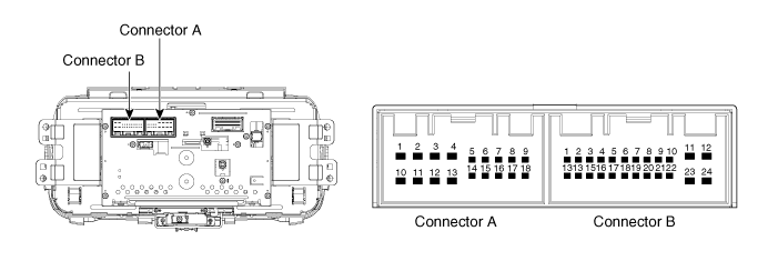
Check the specified condition of terminal.
Tester Connection | Condition | Specified Condition |
CON-B11/B12 ↔ GND (B+) | Always | 9 ~ 16 V |
CON-B18 ↔ GND (ACC) | Always | 9 ~ 16 V |
CON-B23 ↔ GND | Always | Below 1Ω |
CON-B24 ↔ GND | Always | Below 1Ω |
NG | ▶ Check again after repairing or replacing the cable harness or connector. |
R-3 : Check the steering wheel remote control
1.
Check the steering wheel remote control connector specification (Refer to “Audio remote control inspection”)
NG | ▶ Replace the steering wheel remote control switch |
R-4 : Replace the external amplifier
1.
Check the same problems after replacing the external amplifier
OK | ▶ If AVN is normal operating, replace the external amplifier |
NG | ▶ Check the connection of external amplifier power and interface (Refer to R-5, R-6 and R-7) |
R-5 : Check the external amplifier power cable
1.
Remove the external amplifier
2.
Check the specified condition of terminal
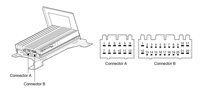
Tester Connection | Condition | Specified Condition |
CON-B10 ↔ GND | Always | 9 ~ 16 V |
CON-B6 ↔ GND | Always | 9 ~ 16 V |
CON-B21 ↔ GND | Always | Below 1Ω |
CON-B22 ↔ GND | Always | Below 1Ω |
NG | ▶ Check again after repairing or replacing the Cable harness or Connector |
R-6 : Check the external amplifier CAN interface
2.
Remove the external amplifier
3.
Check the specified condition of terminal
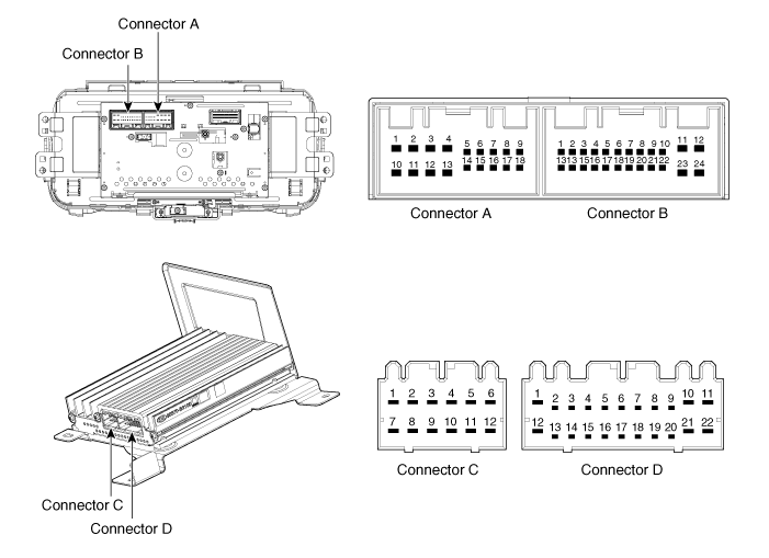
Tester Connection | Condition | Specified Condition |
AVN H/U CON-B1 ↔ EXT. amplifier CON-D8 | Always | Below 1Ω |
AVN H/U CON-B1 ↔ GND EXT. amplifier CON-D8 ↔ GND | Always | Open |
AVN H/U CON-B13 ↔ EXT. amplifier CON-D7 | Always | Below 1Ω |
AVN H/U CON-B13 ↔ GND EXT. amplifier CON-D7 ↔ GND | Always | Open |
NG | ▶ Check again after repairing or replacing the Cable harness or Connector |
R-7 : Check the external amplifier SPDIF connection
2.
Remove the external amplifier
3.
Check the specified condition of terminal

Tester Connection | Condition | Specified Condition |
AVN H/U CON-A6 ↔ EXT. amplifier CON-D19 | Always | Below 1Ω |
AVN H/U CON-A6 ↔ GND EXT. amplifier CON-D19 ↔ GND | Always | Open |
AVN H/U CON-A15 ↔ EXT. amplifier CON-D18 | Always | Below 1Ω |
AVN H/U CON-A15 ↔ GND EXT. amplifier CON-D18 ↔ GND | Always | Open |
NG | ▶ Check again after repairing or replacing the Cable harness or Connector |
R-8 : Check the wiring harness and connector
2.
Remove the external amplifier

Tester Connection | Condition | Specificed Condition |
CON-A5 ↔ Subwoofer2 (+) | Always | Below 1Ω |
CON-A11 ↔ Subwoofer2 (-) | Always | Below 1Ω |
CON-A6 ↔ Subwoofer1 (+) | Always | Below 1Ω |
CON-A12 ↔ Subwoofer1 (-) | Always | Below 1Ω |
CON-A4 ↔ Right side door (+) | Always | Below 1Ω |
CON-A10 ↔ Right side door (-) | Always | Below 1Ω |
CON-A3 ↔ Left side door (+) | Always | Below 1Ω |
CON-A9 ↔ Left side door (-) | Always | Below 1Ω |
CON-B1 ↔ Front center door (+) | Always | Below 1Ω |
CON-B12 ↔ Front center door (-) | Always | Below 1Ω |
CON-A2 ↔ Right front door (+) | Always | Below 1Ω |
CON-A8 ↔ Right front door (-) | Always | Below 1Ω |
CON-A1 ↔ Left front door (+) | Always | Below 1Ω |
CON-A7 ↔ Left front door (-) | Always | Below 1Ω |
NG | ▶ Check again after repairing or replacing the Cable harness or Connector |
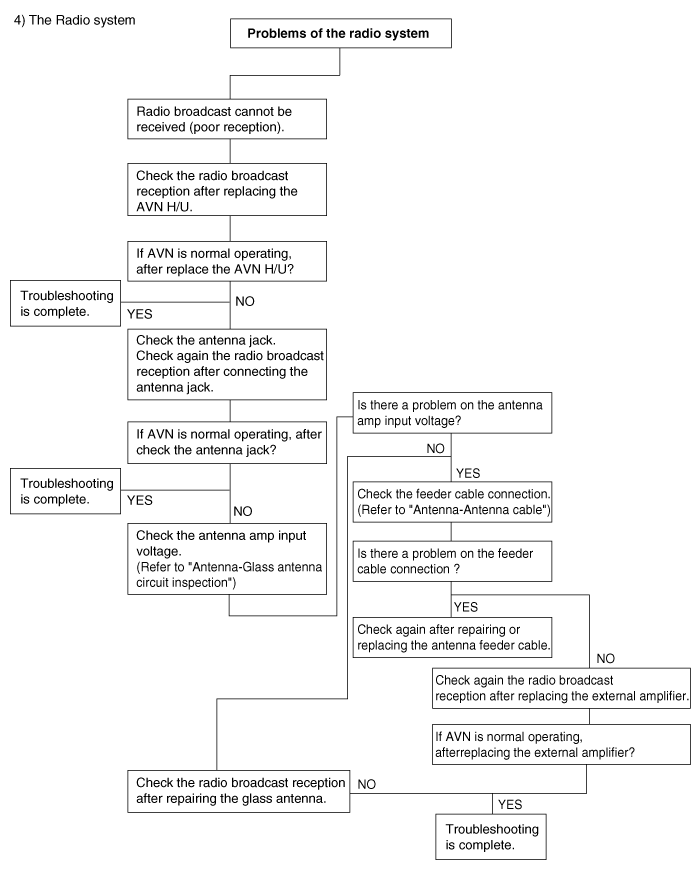
R-9 : Radio broadcast cannot be received (Bad reception)
1.
Check the radio broadcast reception after replacing the AVN H/U
OK | ▶ If AVN is normal operating, replace the AVN H/U |
2.
Check the antenna jack
OK | ▶ Check again the radio broadcast reception after connecting the antenna jack |
3.
Check the antenna amp input voltage (Refer to “Antenna –Glass antenna circuit inspection”)
OK | ▶ Check the antenna amp input voltage (Refer to “Antenna –Antenna cable”) |
4.
Check the feeder cable connection (Refer to “Antenna –Antenna cable”)
OK | ▶ Check again after repairing or replacing the antenna feeder cable. |
5.
Check and repair the roof antenna.
R-10 : Check that speakers are installed tightly
OK | ▶ Install the speakers tightly |
NG | ▶ Install the speakers tightly |
1.
Noise source description
Condition in Which Noise Occurs | Noise Type |
Depressing accelerator pedal increases noise, and stopping engine stops noise immediately | Generator nosie |
When A/C or heater is operating | Blower motor noise |
● When rapidly accelerating on unpaved road ● When engine switch is turned on (IG) | Fuel pump noise |
● When horn switch is pressed and released ● When horn switch is pressed and held down | Horn noise |
Running engine causes soft noise, and stopping engine stops noise immediately | Ignition noise |
Noise occurs synchronously with turn signal flash | Flasher noise |
Noise occurs during window washer operation | Washer noise |
Running engine causes noise, but stopping engine does not stop noise | Engine coolant temperature sensor noise |
When wiper is operating | Wiper noise |
When brake pedal is depressed | Stop light switch noise |
Other | Static electricity on vehicle |
R-11 : Check again after replacing the AVN H/U

1.
Check the input signal of illumination (+)
Tester Connection | Condition | Specificed Condition |
CON-A8 ↔ GND | Always | 9~16 V |
OK | ▶ Check the vehicle wiring |
2.
Check the illumination (-) input signal using the oscilloscope
Tester Connection | Condition | Specificed Condition |
CON-A17 ↔ GND | Always | Check the PWM waveform |
OK | ▶ Check the vehicle wiring and cluster PWM output |
3.
Check the vehicle illumination control unit
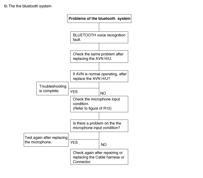
R-12 : Check the microphone input condition

Tester Connection | Condition | Specificed Condition |
CON-B10 ↔ MIC (+) | Always | Below 1Ω |
CON-B22 ↔ MIC (-) | Always | Below 1Ω |
CON-B22 ↔ GND | Always | Open |
OK | ▶ Check the vehicle wiring and microphone |
1.
Test again after replacing the microphone
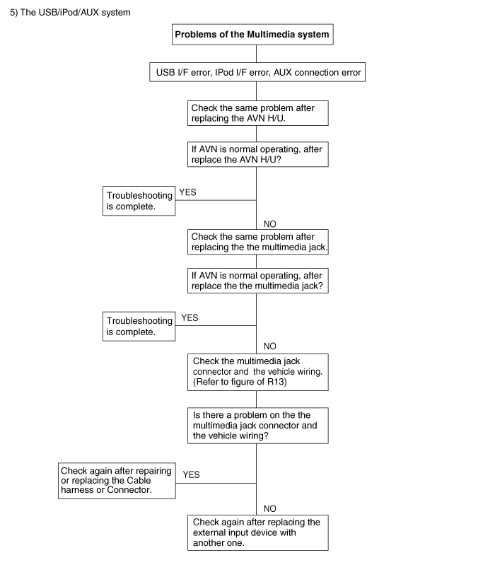
R-13 : Test after replacing the AVN H/U
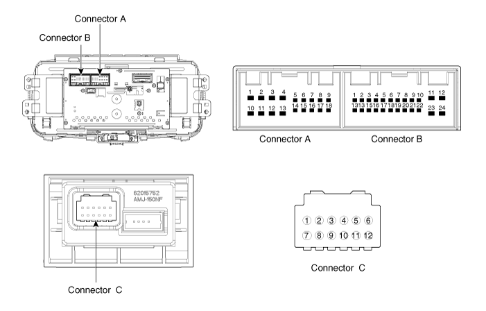
1.
Test after replacing the multimedia jack
OK | ▶ Replace the multimedia jack |
2.
Check the vehicle USB cable.
OK | ▶ Replace the vehicle USB cable |
3.
Check the multimedia jack connector
Tester Connection | Condition | Specificed Condition |
AVN H/U CON-B8 ↔ Multimedia jack CON-C2 | Always | Below 1Ω |
AVN H/U CON-B21 ↔ Multimedia jack CON-C1 | Always | Below 1Ω |
AVN H/U CON-B20 ↔ Multimedia jack CON-C3 | Always | Below 1Ω |
AVN H/U CON-B9 ↔ Multimedia jack CON-C7 | Always | Below 1Ω |
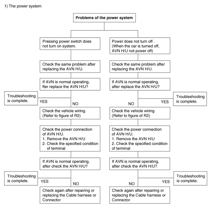
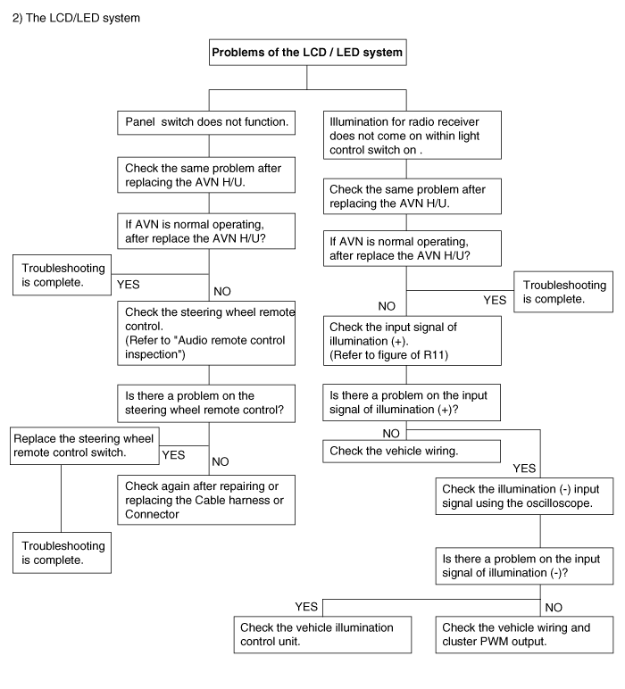
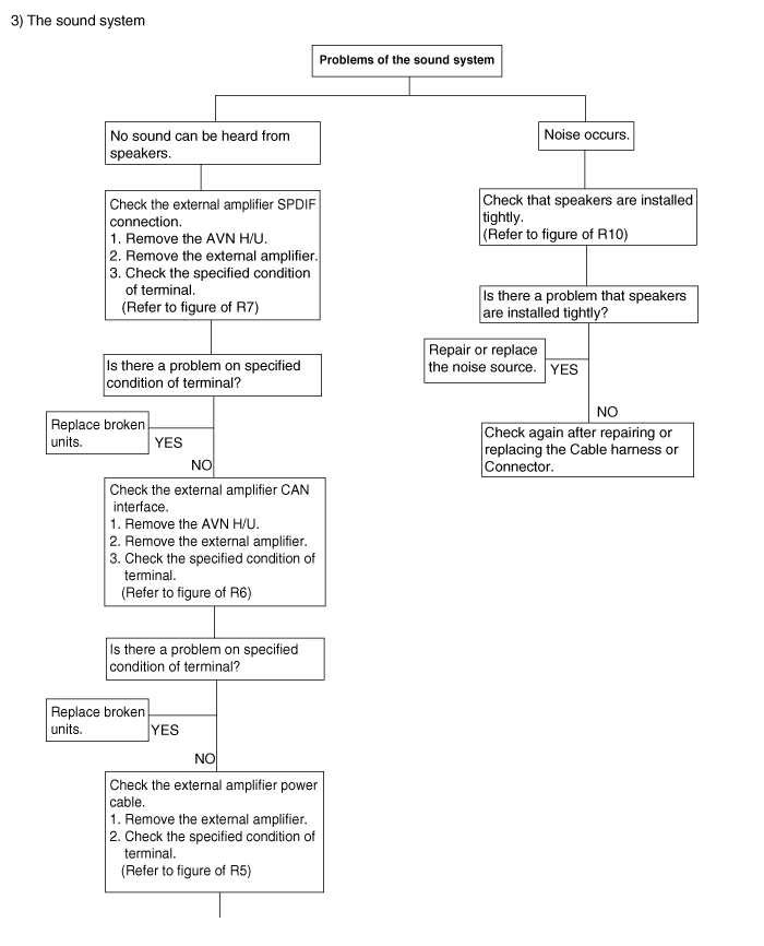
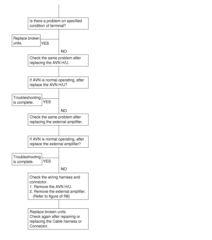
Troubleshooting (Flow chart type)
There are six areas where a problem can occur
: the power system, the LCD/LED system, the sound system, the radio system, the USB/iPod/AUX system, and the bluetooth system.
Troubleshooting enables you to confine the problem to a particular area.
