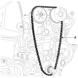
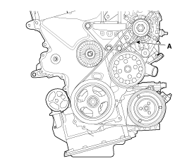
Remove the drive belt.
[HPS Type]
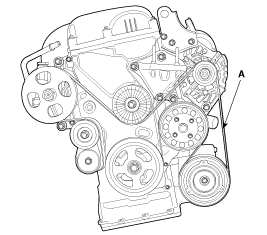
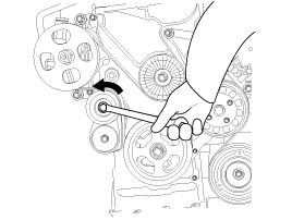
Remove the drive belt by turning the autotensioner counterclockwise.
[MDPS Type]
Loosen the mounting bolts (A) and then, turn the adjusting bolt(B) clockwise in loose tension.
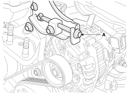
Remove the drive belt (A).
Engine removal is not required for this procedure.
Disconnect the battery negative terminal.
Loosen the water pump pulley bolt and the drive idler mounting bolt.
Remove the drive belt.
[HPS Type]

Remove the drive belt by turning the autotensioner counterclockwise.

[MDPS Type]
Loosen the mounting bolts (A) and then, turn the adjusting bolt(B) clockwise in loose tension.

Remove the drive belt (A).

Remove the alternator (A).(MDPS Type)
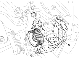
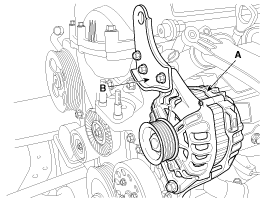
Remove the alternator(A) and bracket(B). (HPS Type)
Remove the RH front wheel.
Remove the engine mounting bracket (A).
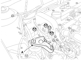
Support the engine with a jack not to be tilted.
Remove the alternator bracket (B).
Remove the engine support bracket (A).
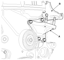
Remove the water pump pulley (A).
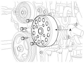
Remove the water pump (A).
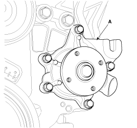
Remove the drive belt idler (A).
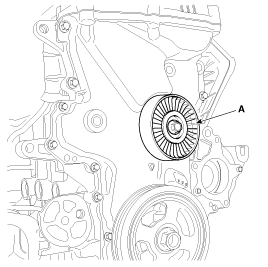
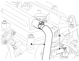
Disconnect the ignition coil connector (A) and the breather hose (B).
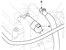
Disconnect the positive crankcase ventilation (PCV) hose (A) and PCSV hose (B).
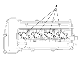
Remove the ignition coils (A).
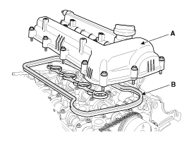
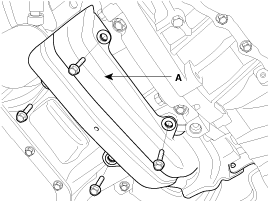
Remove the cylinder head cover (A) with its gasket (B).
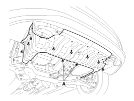
Remove the under covers (A).
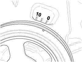
Turn the crankshaft pulley clockwise, and align its groove with the timing mark of the timing chain cover.
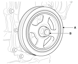
Remove the crankshaft bolt (B) and crankshaft pulley (A).
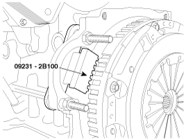
There are two methods to hold the ring gear when installing or removing the crankshaft damper pulley.
Install the SST (09231-2B100) to hold the ring gear after removing the starter.
Install the SST (09231-3D100) to hold the ring gear after removing the dust cover.
Remove the bracket (A).
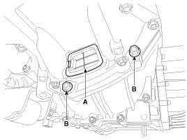
Remove the dust cover (A) on the bottom of the ladder frame and unfasten the transaxle mounting bolt (B).
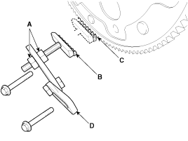
Adjust the length of the holder nuts (A) so that the front plate of the holder (B) puts in the ring gear (C) teeth.
Adjust the angle of the links (D) so that the bolt 70mm (2.7559in.) can be fastened to the original mounted hole.
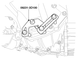
Install the SST (09231-3D100) using the mounting bolts and spacers. Tighten the bolts and nuts of the holder and links securely.
Remove the timing chain cover (A).

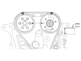
Align the timing marks of the camshaft sprocket with the upper surface of the cylinder head to make No.1 cylinder be positioned at TDC.
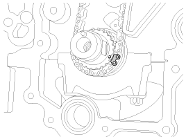
Check the dowel pin of the crankshaft for facing upside of the engine at this monent.
Put paint marks on the timing chain links(3 places) that meet with the timing marks of the camshaft sprockets(In, Ex : 2) and the crankshaft sprocket.
Remove the hydraulic tensioner (A).
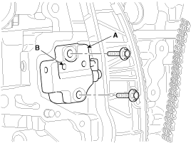
Before removing the tensioner, fix the piston of the tensioner with a pin through the hole(B) at TDC.
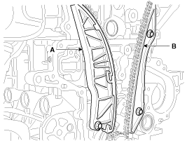
Remove the timing chain tensioner arm (A) and guide (B).
Remove the timing chain (A).
