
Each control module such as BCM(Body Control Module), Cluster(CLU:Cluster), SMK(Smartkey Module), SJB(Smart Junction Box), PSM(Power Seat Module) is connected each other with Body CAN*¹. Each Control Unit(Module) consists of Low and High Line.
*¹ CAN (Controller Area Network) : CAN is serial bus communication type which links not only communication system but also control units each other.
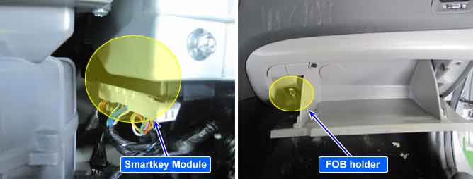
The Fob holder has the μ SW which recognizes an insertion between Immo. Antenna and Fob key for the TP Comunictions. it makes to possible that you could proceed to make an emregency start when the vehilce's battery is discharged from the discommunitcations of a LF siganl.
This code is outputted when the immobilizer data circuit is shorted to ground.
(In this case, it is not possible to get authorization although the fob is in the holder.)
Item | Detecting Condition | Possible Cause |
DTC Strategy |
•
Immobilizer data line check (by voltage monitoring) | 1. Short to ground in immobilizer data circuit |
Enable Conditions |
•
The communication state between the fob and the fob holder when SSB button is pushed. (The fob is in the holder.) | |
Threshold Value |
•
Short to ground in immobilizer data circuit (2V and below) | |
Diagnostic Time |
•
Immediately | |
DTC Erasing Time |
•
DTC is erased immediately after trouble fixed. (After communication recovery) |