Each control module such as BCM(Body Control Module), Cluster(CLU:Cluster), SMK(Smartkey Module), SJB(Smart Junction Box), PSM(Power Seat Module) is connected each other with Body CAN*¹. Each Control Unit(Module) consists of Low and High Line.
With these two communication Line, They controls body electrical by communicate mutual information.
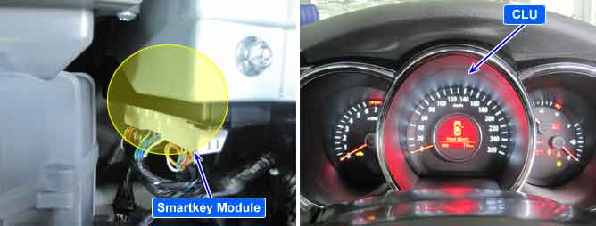
SMK ECU and CLU communicates each other in order to recognize engine condition, engine coolant temperature,vehicle speed and shift lever position etc.
This code is outputted when CLU can't receive data from SMK by CAN Line for 10 sec.
Item | Detecting Condition | Possible cause |
DTC Strategy |
•
CAN Comm. Check (CLU ↔ SMK) | 1. Poor Connection 2. Power source to CLU 3. Short to battery in CAN communication 4. Short to ground in CAN communication 5. Short between CAN high and CAN low each other 6. Faulty Smartkey Module 7. Faulty each modules |
Enable Conditions |
•
SMK IGN ON or Engine ON | |
Threshold value |
•
No message from SMK to CLU for 10 sec. | |
Fail safe |
•
DTC is erased immediately after receiving data from SMK. |