Connect "A/T solonoid valve"connector and Scantool to Data Link Connector(DLC).
Engine ON and operate Vehicle Speed Sensor(Output speed sensor).
Measure waveform between signal of Vehicle Speed Sensor(Output speed sensor) harness and chassis ground.
Specification : See specific waveform
Is the measured waveform within specifications?
![]() | ▶ Thoroughly check connectors for looseness, poor connection, bending, corrosion, contamination, deterioration, or damage. Repair as necessary and go to "Verification Vehicle Repair" procedure. |
![]() | ▶ Go to"PCM/TCM Inspection" procedure. |
Ignition off & Engine Off.
Disconnect "ATM solenoid valve connector.
Connect scantool to Data Link Connector(DLC) and select Simulation mode.
Input specific frequency to signal of Vehicle Speed Sensor(Output speed sensor) by simulation mode.
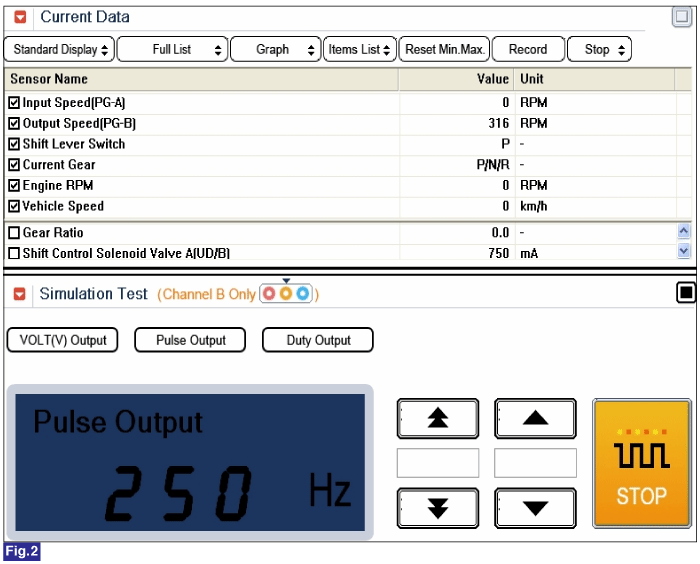
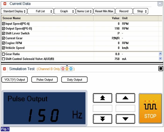
Fig.1) OUTPUT 150Hz → 190rpm
Fig.2) OUTPUT 250Hz → 316rpm
※ The values are subject to change according to vehicle model or conditions
Is measured Vehicle Speed Sensor(Output speed sensor) value changed by Output frequency of Scantool?
![]() | ▶ Substitute with a known-good Vehicle Speed Sensor(Output speed sensor) and then go to "Verification of Vehicle Repair" procedure. |
![]() | ▶ Substitute with a known-good PCM/TCM and check for proper operation.If the problem is corrected, replace PCM/TCM and then go to "Verification of Vehicle Repair" procedure. |