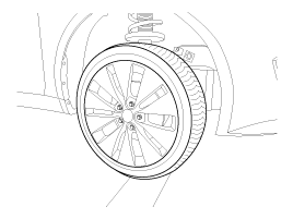
1.
Remove the front wheel & tire.
Tightening torque:
88.3 ~ 107.9N.m (9.0 ~ 11.0kgf.m, 65.1 ~ 79.6lb-ft)
caution
Be careful not to damage to the hub bolts when removing the front wheel & tire.
Remove the front wheel & tire.
Tightening torque:
88.3 ~ 107.9N.m (9.0 ~ 11.0kgf.m, 65.1 ~ 79.6lb-ft)
Be careful not to damage to the hub bolts when removing the front wheel & tire.
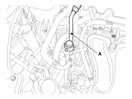
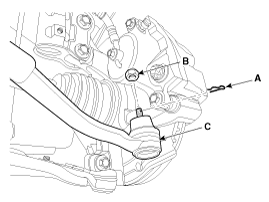
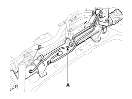
Disconnect the pressure hose (A), pressure switch (B), return hose (C) and then drain the power steering fluid.
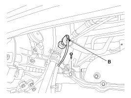
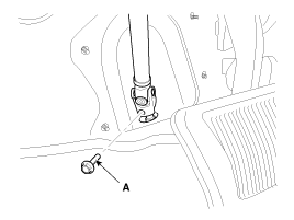
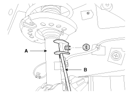
Loosen the bolt (A) and then disconnect the universal joint assembly from the pinion of the steering gear box.
Tightening torque:
29.4 ~ 34.3N.m (3.0 ~ 3.5kgf.m, 21.7 ~ 25.7lb-ft)
Lock the steering wheel in the straight ahead position to prevent the damage of the clock spring inner cable when you handle the steering wheel.
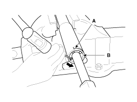
Remove the tie rod end ball joint (C) from the knuckle by using the SST (09568-34000).
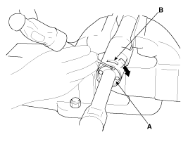
Remove the split pin (A).
Remove the castle nut (B).
Use the SST (09568-34000).
Tightening torque:
34.3 ~ 44.1N.m (3.5 ~ 4.5kgf.m, 25.3 ~ 32.5lb-ft)
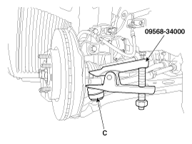
When using SST, be sure not to damage the dust cover of lower arm ball joint.
Keep SST tied to the car because there is a risk of injury by dropping the SST during removing the lower arm ball joint.
The peripheral parts may be damaged when removing the lower arm ball joint with a general tool such as lever, so be sure to use SST.
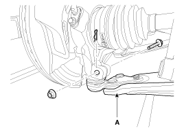
Loosen the bolt & nut and then remove the lower arm (A).
Tightening torque:
98.1 ~ 117.7N.m (10.0 ~ 12.0kgf.m, 72.3 ~ 86.8lb-ft)
Disconnect the stabilizer link (B) from the front strut assembly (A) after loosening the nut.
Tightening torque:
98.1 ~ 117.7N.m (10.0 ~ 12.0kgf.m, 72.3 ~ 86.8lb-ft)
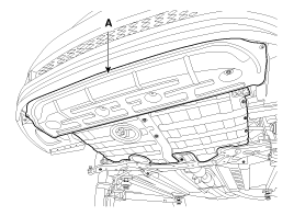
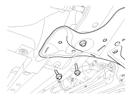
Remove the under cover (A).
Loosen the bolt (A) & nut (B) and then remove the roll rod stopper.
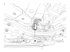
Disconnect the muffler rubber hanger (A).
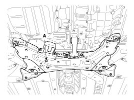
Loosen the bolts & nuts and then remove the sub frame.
Tightening torque
Sub frame mounting bolts & nuts:
156.9 ~ 176.5N.m (16.0 ~ 18.0kgf.m, 115.7 ~ 130.2lb-ft)
Sub frame stay bolts & nuts:
44.1 ~ 58.8N.m (4.5 ~ 6.0kgf.m, 32.5 ~ 43.4lb-ft)
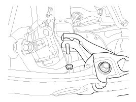
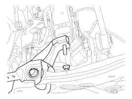
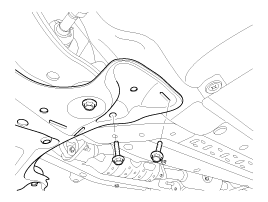
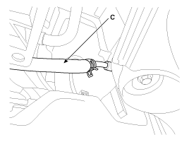
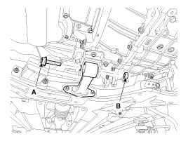
Loosen the bolt and then remove the steering gearbox (A).
Tightening torque:
88.3 ~ 107.9N.m (9.0 ~ 11.0kgf.m, 65.1 ~ 79.6lb-ft)
Installation is the reverse of the removal.
Add power steering fluid to reservoir.
Bleed the power steering system.
(Refer to Air bleeding)
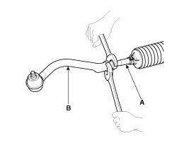
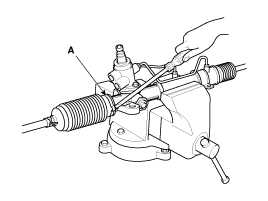
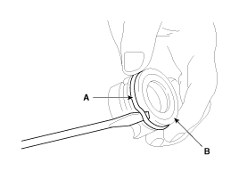
Remove the tie rod end (B) from the tie rod (A).
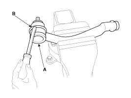
Remove the dust cover (B) from the ball joint (A).
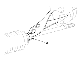
Remove the bellows band (A).
Remove the bellows clip (A).
Pull the bellows out toward the tie rod.
Check for rust on the rack when the bellows are replaced.
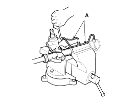
Remove the feed tube (A) from the rack housing.
While moving the rack slowly, drain the fluid from the rack housing.
Un stake the tab washer (A) which fixes the tie rod (B) and rack (C) with a chisel.
Remove the tie rod (B) from the rack (A).
Remove the tie rod (B) from the rack (A), taking care not to twist the rack.
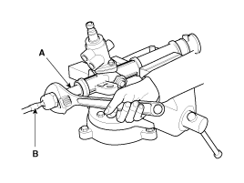
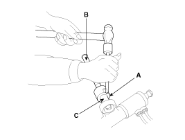
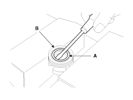
Remove the yoke plug locking nut (A).
Remove the yoke plug (B) with a 14mm socket (A).
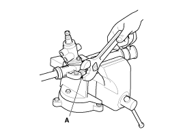
Remove the lock nut (D), yoke plug (C), rack support spring (B) and rack support yoke (A) from the gear box.
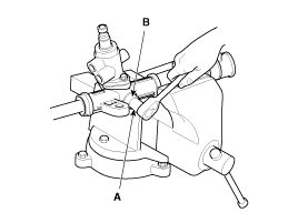
When the end of the circlip comes out of the notched hole of the housing rack cylinder, turn the rack stopper (A) clockwise and remove the circlip.
Be careful not to damage the rack.
When the end of the circlip comes out of the notched hole (A) of the housing rack cylinder, turn the rack stopper (B) counterclockwise end remove the circlip.
Be careful not to damage the rack.
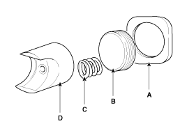
Remove the rack bushing and rack from the rack housing.
Remove the O-ring (A) from the rack bushing (B).
Remove the oil seal (B) from the rack bushing (A).
Remove the valve body (A) from the valve body housing (B) with a soft hammer.
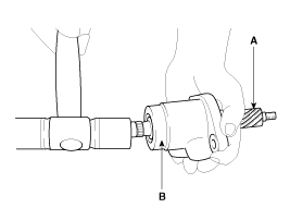
Using the special tool, remove the oil seal and ball bearing from the valve body.
Remove the oil seal and O-ring from the rack housing.
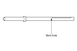
Be careful not to damage the pinion valve cylinderinside of the rack housing.
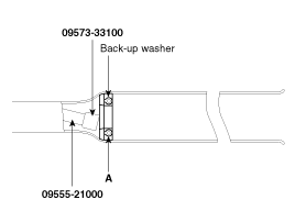
Using the special tool(09573-33100, 09555-21000), remove the oil seal (A) from the rack housing.
Be careful not to damage the rack cylinder insideof the rack
Reassembly is the reverse of the disassembly.
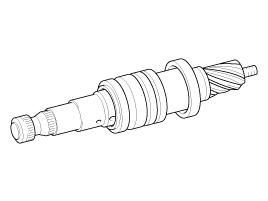
Rack
Check for rack tooth face damage or wear.
Check for oil seal contact surface damage.
Check for rack bending or twisting.
Check for oil seal ring damage or wear.
Check for oil seal damage or wear.
Pinion
Check for pinion gear tooth face damage or wear.
Check for oil seal contact surface damage.
Check for seal ring damage or wear.
Check for oil seal damage or wear.
Bearing
Check for seizure or abnormal noise during a bearing rotation.
Check for excessive play.
Check for missing needle bearing rollers.
Others
Check for damage of the rack housing cylinder bore.
Check for boot damage, cracking or aging.
