3.
Measure the voltage between "ST" terminal of the starter and battery (-) terminal.
■ Specification : B+
Remove start relay and "ST" terminal of the starter.
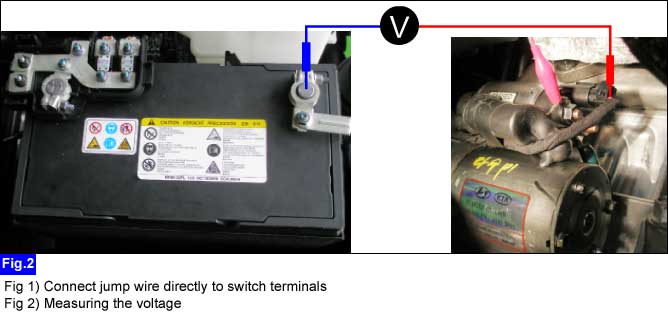
Connect jump wire directly to switch terminals of the start relay(RLY3) on theE/R fuse & relay box.
Measure the voltage between "ST" terminal of the starter and battery (-) terminal.
■ Specification : B+
Is measured voltage within the specification?
 | ▶ Go to "Start relay control circuit inspection" procedure as below. |
 | ▶ Check for IGN2(30A) fuse blown or poor connection. ▶ Check for E/R fuse & relay box. ▶ Check for open circuit between 'ST' terminal of the starter and E/R fuse & relay box. |
Measure the voltage between coil power supply terminal of the start relay(RLY3) and chassis ground at IG key "START".
■ Specification : B+
Is measured voltage within the specification?
| ▶ Check for start relay coil ground control from PCM(A/T) at start. ▶ Check for ignition lock switch.(M/T) ▶ Check for start relay. |
| ▶ Check for ignition switch, start fues(7.5A). ▶ Check for burglar alarm relay. ▶ Chekck for IPS control module. |
Measure the voltage between coil power supply terminal of the start relay(RLY.3) and chassis ground at IG key "START".
■ Specification : B+
Is measured voltage within the specification?
| ▶ Check for open circuit between start relay(#3) and chassis ground. ▶ Check for start relay(#3) coil ground control from PCM(A/T) at start. ▶ Check for start relay(#3). |
| ▶ Check for F12 fues(10A) in the E/R fuse & relay box and F34(7.5A), F9(7.5A) in the IP junction box. ▶ Check for Start relay(#6) control from PCM at start. ▶ Chekck for power supply from PDM to Start relay(#6). ▶ Check for start relay control related with SMART KEY system(PDM). |
