1.
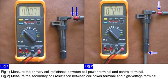
Measure primary coil resistance and secondary coil resistance after disconnecting ignition coil connector.
■ Specification :
Primary coil resistance | 0.62 ± 10%(20℃) |
Secondary coil resistance | 7.0 ㏀ ± 15% (20℃) |
Measure primary coil resistance and secondary coil resistance after disconnecting ignition coil connector.
■ Specification :
Primary coil resistance | 0.62 ± 10%(20℃) |
Secondary coil resistance | 7.0 ㏀ ± 15% (20℃) |
Is the primary (secondary) resistance of the ignition coil normal?
 | ▶ Go to "Ignition coil power circuit inspection " procedure as below. |
 | ▶ Replace the ignition coil. |
Measure the voltage between power terminal of the ignition coil harness connector and chassis ground with IG key "ON" after disconnecting ignition coil connector.
■ Specification : B+
Is the voltage within the specification?
| ▶ Go to "Ignition coil control circuit inspection" procedure. |
| ▶ Thoroughly check connectors for looseness, poor connection, bending, corrosion, contamination, deterioration, or damage. ▶ Check for open circuit in the power circuit between power terminal of the ignition coil harness connector and power terminal of the ECM harness connector. ▶ Check for short to ground in the power circuit between power terminal of the ignition coil harness connector and power terminal of the ECM harness connector. |
Connect the red tongs of the LED circuit tester to battery(+) and probe of LED circuit tester to control terminal of the ignition coil connector after disconnecting ignition coil connector.
Perform actuation test(ignition coil #1~#4) of the Ignition coil.
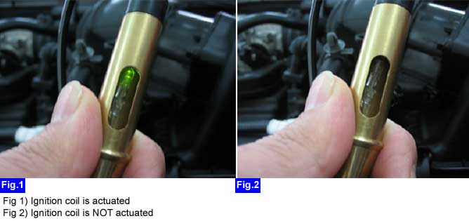
Is the LED circuit tester lit (When Ignition coil is operated by actuation test)?
| ▶ Go to "Ignition coil waveform inspection" procedure as below. |
| ▶ Thoroughly check connectors for looseness, poor connection, bending, corrosion, contamination, deterioration, or damage. ▶ Check for open circuit in the control circuit between control terminal of the ignition coil harness connector and control terminal of the ECM harness connector. ▶ Check for short to ground in the between control terminal of the ignition coil harness connector and control terminal of the ECM harness connector. ▶ Substitute with a known-good ECM and check for proper operation. If the problem is corrected, Replace the ECM. |
Select oscilloscope function on the GDS and Connect channel A of the VMI to ignition coil connecter.
Measure the primary ignition coil signal waveform with IG key "START".
■ Specification :
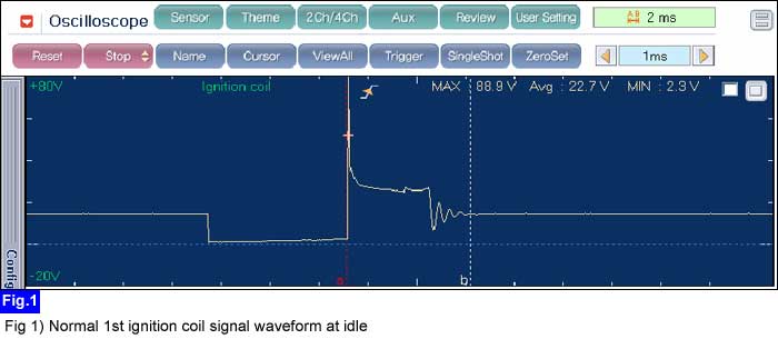
Is the primary ignition coil waveform normal?
| ▶ Go to "ETC system inspection" procedure. ▶ Go to "Vehicle speed sensor inspection" procedure. ▶ Go to "Damper clutch inspection" procedure. |
| ▶ Replace the ignition coil. |
