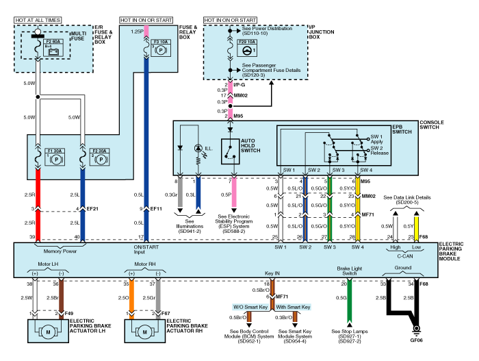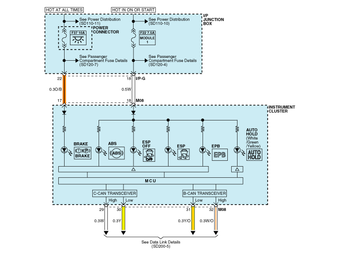


Pin No. | Function | Pin No. | Function |
1 | - | 21 | Gear switch |
2 | - | 22 | - |
3 | - | 23 | CAN_Low |
4 | - | 24 | CAN_High |
5 | - | 25 | EPB switch 1 |
6 | - | 26 | EPB switch 2 |
7 | - | 27 | EPB switch 3 |
8 | - | 28 | EPB switch 4 |
9 | - | 29 | - |
10 | - | 30 | - |
11 | - | 31 | - |
12 | - | 32 | - |
13 | - | 33 | ground |
14 | - | 34 | ground |
15 | - | 35 | Rear right caliper motor + |
16 | - | 36 | Rear left caliper motor - |
17 | Ignition 1 | 37 | Rear right caliper motor - |
18 | Key in switch | 38 | Rear left caliper motor + |
19 | - | 39 | Rear left motor power |
20 | Brake light switch] | 40 | Rear right motor power |