
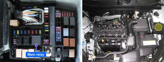
The PCM provides ground to one side of the coil of the main relay and the other side is connected to the battery. The PCM monitors battery voltage and the voltage after the main relay.
The PCM measures the voltage from ignition key and from main relay respectively and compares two voltages. This comparison will watch if the Main Relay has switched and remains on after ignition Key-On and if it has switched off after the ignition Key-Off. The PCM sets DTC P0560 if the voltage after Main Relay is lower than a predetermined threshold after ignition key-on or higher than a predetermined threshold after ignition key-off.
Item | Detecting Condition | Possible Cause | |
DTC Strategy | Case1 |
•
Comparison of battery voltage and voltage after main relay(Voltage low) | 1. Open or short circuit 2. Poor connection or damaged harness |
Case2 |
•
Comparison of battery voltage and voltage after main relay(Voltage high) | ||
Case3 |
•
Monitor voltage supply after main relay(open circuit check) | ||
Enable Conditions | Case1 |
•
Ignition "ON"
•
Battery voltage > 10V
•
Delay time after main relay ON > 0.05 Seconds | |
Case2 |
•
Ignition "OFF"
•
Delay time after main relay ON > 0.05 Seconds | ||
Case3 |
•
Voltage after main relay > 8.5V
•
Voltage after ignition switch > 5V
•
Delay time after main relay ON > 0.05 Seconds | ||
Threshold Value | Case1 |
•
Voltage after Main Relay < 6 V | |
Case2 |
•
Voltage after Main Relay < 6 V | ||
Case3 |
•
Voltage after main relay - Voltage after ignition switch > 3.8~8.5V | ||
Diagnostic Time | Case1 |
•
0.2 Seconds | |
Case2 |
•
0.2 Seconds | ||
Case3 |
•
0.1 Seconds | ||
MIL On Condition |
•
- | ||