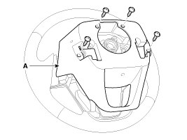
Remove the steering wheel cover (A) after loosening the screws.
Disconnect the battery negative terminal.
Remove the driver airbag module. (Refer to the RT group - "Airbag module")
Remove the steering wheel. (Refer to the ST group - "Steering column and shaft")
Remove the steering wheel cover (A) after loosening the screws.

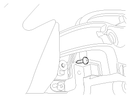
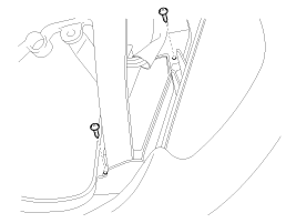
loosening the screws at rear side of switch.
Disconnect the cruise control switch connector and then remove the switch (A).
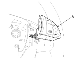
Be careful not to damage the hook when removing the switch.
Install in the reverse order of removal.
Disconnect the cruise control switch connector from the control switch.
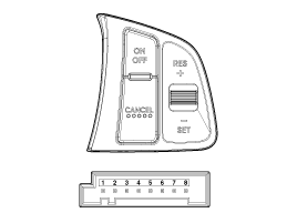
Measure resistance between terminals on the control switch when each function switch is ON (switch is depressed).
Function switch | Terminal | Resistance |
CANCEL | 2 - 7 | 180Ω ± 5% |
SET/– | 2 - 7 | 330Ω ± 5% |
RES/+ | 2 - 7 | 550Ω ± 5% |
ON/OFF | 2 - 7 | 880Ω ± 5% |
If not within specification, replace switch.
Connect the cruise control switch connector to the control switch.
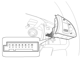
With ignition switch ON, measure voltage between terminals on the harnessside connector when each function switch is ON (switch is depressed).
Function switch | Terminal | Voltage |
CANCEL | 2 - 7 | 0.67 ~ 0.86V |
SET/– | 2 - 7 | 1.10 ~ 1.39V |
RES/+ | 2 - 7 | 1.59 ~ 1.97V |
ON/OFF | 2 - 7 | 2.13 ~ 2.56V |
If not within specification, inspect the control switch resistance. The measuring resistance value is not within specification, replace the switch and measure the voltage again.
If resistance is OK but, measuring voltage is not within specification, inspect the wiring harness and connectors between the switch and the instrument cluster .