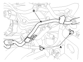
Release the vacuum pipe assembly (B) after removing the bolt (A).

Connect the GDS to the Data Link Connector (DLC).
Measure the CVVL lift value in the IG ON and the idle condition.
Conditions | Lift value (mm) |
IG ON | 6 ~ 9 |
Idle (Engine warm up, 650 rpm) | 1 |
The Lift value moves to 9mm lift when IG OFF.
If it is not reached to 9 mm by mechanic friction, check if the lift value is normal in the engine warm up condition while repeating IG ON/OFF 3~4 times.
Check sensor / wheel interference, damage, foreign matter.
Check connector connection, wiring open/short, contamination.
Turn the ignition switch OFF and disconnect the negative (-) cable.
Remove the air intake hose.
(Refer to Engine Mechanical system - "Engine and transaxle assembly”)
Release the vacuum pipe assembly (B) after removing the bolt (A).

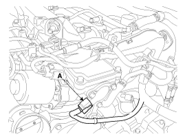
Disconnect the CVVL position sensor connector (A).

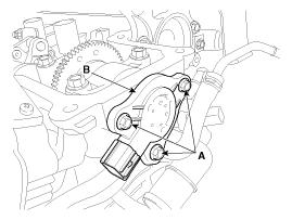
Remove CVVL position sensor (B) after removing the bolt (A).

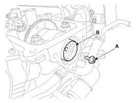
Remove the magnet wheel (B) after removing the installation bolt (A).

Install the component with the specified torques.
Note that internal damage may occur when the component is dropped. If the component has been dropped, inspect before installing.
Be careful not to enter foreign matter into the sensor and cylinder head.
Apply dry solvents, spindle oil, gasoline to the sensor O-ring.
Tighten the bolt (B) after inserting the lug of the magnet wheel (A) into groove of the shaft completely.
Do not re-use the O-ring.
Be careful not to contact foreign matter to the surface of the magnet when installing the magnet wheel.
Replace the sensor and the magnet together at the same time when replacing those.
Be careful not to install O-ring incorrectly.
Install the CVVL position sensor in the reverse of removal.
Vacuum pipe assembly installation bolt: 9.8 ~ 11.8 N.m (1.0 ~ 1.2 kgf.m, 7.2 ~ 8.7 lb-ft)
CVVL position sensor installation bolt: 9.8 ~ 11.8 N.m (1.0 ~ 1.2 kgf.m, 7.2 ~ 8.7 lb-ft)
Magnet wheel installation bolt: 9.8 ~ 11.8 N.m (1.0 ~ 1.2 kgf.m, 7.2 ~ 8.7 lb-ft)
After reinstalling or replacing the CVVL position sensor, the sensor position should be reset for normal operation of the system. Perform “Learning for CVVL valve lift adaptation values” with the GDS diagnostic tool.
(Refer to “Learning for CVVL valve lift adaptation values” in Engine Mechanical System - Engine and Transaxle assembly)