Component Inspection
■ RCV Control Solenoid Valve Coil Resistance Inspection
1.

Ignition "OFF".

2.

Disconnect Battery (-) terminal.

3.

Refer to "Shop Manual" and disconnect RCV Control Solenoid Valve connector.

4.

Measure resistance between Pin No. 2 (Power) terminal and Pin No. 1 (Control) terminal of RCV Control Solenoid Valve component.

Specification : Approx. 28.3 ~ 31.1Ω at 20℃(68℉)

5.

Is measured value within specification?

▶ Go to "RCV Control Solenoid Valve Actuation Test" procedure.

▶ Carefully re-do this troubleshooting guide steps.

▶ If problem still occurs, replace RCV Control Solenoid Valve and then go to "Verification of Vehicle Repair" procedure.

caution

Do not apply oil when hose assembled.

The hose should be inserted perfectly to nipple.
■ RCV Control Solenoid Valve Actuation Test
6.

Connect GDS to Data Link Connector(DLC).

7.

Ignition "ON" & Engine "OFF"

8.

Perform "TCI Bypass Valve" in "Actuation Test" with GDS.

9.

Monitor "TCI Bypass Valve Activation" parameter in "Current Data" with GDS.

Specification : Operating sound(Clicking sound) is heard

10.

Is the parameter displayed within specification?

▶ Fault might be intermittent and caused either by poor contact in connectors or wiring harness, or it has been repaired and control module memory is not cleared yet. Thoroughly check terminal of battery, all connectors ( and connections) for looseness, bending, corrosion, contamination, deterioration, and/or damage.

▶ Repair or replace as necessary and then go to "Verification of Vehicle Repair" procedure.

▶ Carefully re-do this troubleshooting guide steps.

▶ If problem still occurs, replace RCV Control Solenoid Valve and then go to "Verification of Vehicle Repair" procedure.

caution

Do not apply oil when hose assembled.

The hose should be inserted perfectly to nipple.

■ Boost Pressure Sensor (BPS) inspection
11.

Ignition "OF Ignition

12.

Connect GDS to Data Link Connector(DLC).

13.

"ON" & Engine "ON"

14.

Warm up the engine to normal operating temperature.

15.

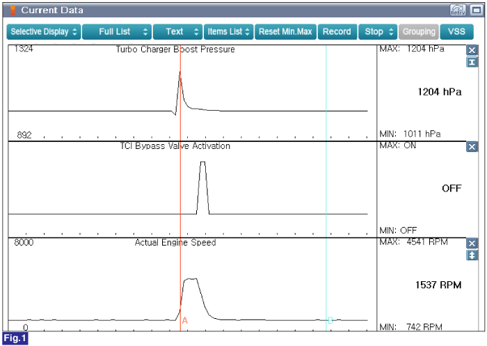
Monitor following parameters in "Current Data" with GDS.

Specification : Refer to Figure below

Fig. 1) Boost pressure increases as engine speed increases.

16.

Is parameter displayed within specification?

▶ Carefully re-do this troubleshooting guide steps.

▶ If problem still occurs, replace Turbocharger assembly and then go to "Verification of Vehicle Repair" procedure.

▶ Carefully re-do this troubleshooting guide steps.

▶ If problem still occurs, replace Boost Pressure Sensor (BPS) and then go to "Verification of Vehicle Repair" procedure.

Яндекс.Метрика