
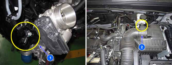
1. MAP & IATS
2. MAF
MAPS(Manifold Absolute Pressure Sensor) calculates indirectly the amount of air flow by measuring the intake pressure, and it is called Speed-Density Type. MAPS sends PCM the analog output signals which is proportional to absolute pressure by pressure change, and PCM uses these signals to calculate the amount of air flow with engine RPM.
MAFS(Mass Air Flow Sensor) is a hot-film type, and is mounted between air-cleaner and throttle body, which measures the amount of air flow getting into the engine. It is composed of tube, sensor assembly, and honey cell. Once the laminar stream which was generated by honey cell flows around the hot-film, the convective heat transfer is generated from hot-film, and the energy loss of MAFS is generated by this heat transfer. ECU calculates the amount of intake air flow using measuring this energy loss.
CVVL uses both of MAPS and MAFS, and if the error between these values is large, ECU can't control accurately the amount of air flow and ECU sets P006A.
Item | Detecting Condition | Possible cause |
DTC Strategy |
•
The relative ratio of the values of air flow measured by MAPS and MAFS is large excessively. | 1. MAP Sensor 2. MAF Sensor 3. Poor connection 4. Open circuit of power line or short circuit to ground 5. Open circuit of signal line or short circuit to ground |
EnableConditions |
•
Engine RPM is higher than 580 and lower than 6500.
•
Battery voltage is higher than 10V and lower than 16V.
•
Relative quantity of flow of canister in cylinder is lower than 8%.
•
Engine oil temperature is lower than 230℉
•
Not fuel cut
•
Engine running time is longer than 10 sec.
•
No relative DTCs | |
Threshold value |
•
Battery sensor error | |
Diagnosis Time |
•
Relative air flow ratio is lower than -25 ~ -70% depended on the amount of air flow.
•
Relative air flow ratio is higher than 25 ~ 70% depended on the amount of air flow. | |
MIL On Condition |
•
Second driving cycle (MIL On) |
MAPS(Kpa) | Output voltage(V) |
20 | 0.79 |
46.66 | 1.84 |
101.32 | 4 |
MAFS(Kg/h) | MAFS signal(Hz) |
10 | 2012.7 |
12 | 2055 |
15 | 2116 |
20 | 2209.4 |
30 | 2370 |
40 | 2507.8 |
50 | 2631.3 |
60 | 2745.6 |
75 | 2906 |
90 | 3508 |
105 | 3204.7 |
120 | 3348.5 |
140 | 3537.9 |
160 | 3727 |
190 | 4013.9 |
- Check whether the value of MAPS increases when the throttle position sensor is accelerated and vice versa.
- Normal waveform of MAFS at idle.
- Normal waveform of MAFS at acceleration.