Ignition "ON" & Engine "ON".

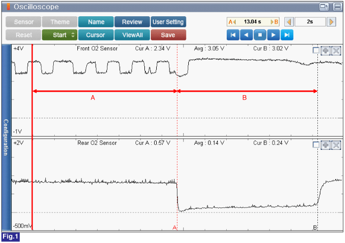
Fig.1) Upstream O2 Sensor and Downstream O2 sensor Signal waveform (Warm-up Condition)
A : Approx. 2500 RPM.
B : Fuel Cut after acceleration.
Ignition "OFF".
Connect VMI to GDS and set up an oscilloscope as follow (4-channel);
Channel A (+) : Pin No. 3 (V_IP) terminal of Upstream O2 Sensor.
Channel A (-) : Ground
Channel B (+) : Pin No. 1 (Signal) terminal of Downstream O2 Sensor.
Channel B (-) : Ground
Ignition "ON" & Engine "ON".

Fig.1) Upstream O2 Sensor and Downstream O2 sensor Signal waveform (Warm-up Condition)
A : Approx. 2500 RPM.
B : Fuel Cut after acceleration.
Is measured value within specficiation?
 | ▶ Fault might be intermittent and caused either by poor contact in connectors or wiring harness, or it has been repaired and control module memory is not cleared yet. Thoroughly check terminal of battery, all connectors ( and connections) for looseness, bending, corrosion, contamination, deterioration, and/or damage. ▶ Repair or replace as necessary and then go to "Verification of Vehicle Repair" procedure. |
 | ▶ Carefully re-do this troubleshooting guide steps. ▶ If no problems were found with the circuits or connectors, Replace the Downstream O2 Sensor and then go to "Verification of Vehicle Repair" procedure. |
Install the component with the specified torques.
Note that internal damage may occur when the component is dropped or mis- treated.
DO NOT use a cleaner, spray, or grease to sensing element and connector of the sensor because oil component in them may cause malfunction or affects on sensor performance.
Sensor and its wiring may be damaged in case of contacting with the exhaust system(Exhaust Manifold, Catalytic Converter, and others).