
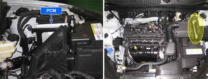
For each injector cycle, the Powertrain Control Module(PCM) has four phases.
First, the PCM "Pre-energizes" the injector circuit with 12 volts for a specified amount of time.
Then, the PCM sends a "peak" voltage of 55 volts, which causes the Injector to begin mechanically opening.
The PCM will then "hold" the current at a lower voltage until the injector is completely open.
Once the injector is completely open, the PCM will "duty cycle" the current to maintain the open position.
The length of the duty cycle will vary due to RPM and load conditions.
The injector will quickly close once the PCM discontinues current.
P0611 is set when there is an internal error in the fuel injector control driver.
Item | Detecting Condition | Possible Cause |
DTC Strategy |
•
Electrical Check | 1. INJECTOR circuit 2. Fuel Injector Control Driver |
Enable Conditions |
•
Fuel injector control driver performance internal electronic failure | |
Threshold Value |
•
Bus communication error detected by ECU-hardware | |
Diagnostic Time |
•
1.5 Seconds | |
MIL On Condition |
•
2 Drive Cycles |
Coil Resistance (Ω) | Temp (℃) | Temp (℉) |
1.25 | 20 | 68 |
Fuel injector control module
Ch A : INJ HIGHSIDE signal during fuel injection (Normal idle state)
Ch B : INJ LOWSIDE signal during fuel injection (Normal idle state)