6.
Erase DTC.
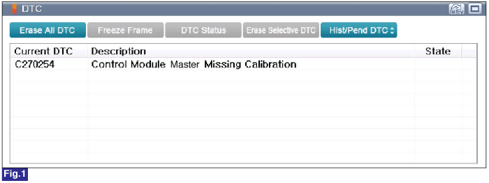
Fig.1) Diagnostic Trouble Code(DTC) is shown above
IG "OFF".
Connect GDS.
IG "ON" and engine "OFF".
Select "Diagnostic Trouble Codes(DTC)" mode.
Check for any DTCs on the "Diagnostic Trouble Code(DTC)" with GDS.
Erase DTC.
Fig.1) Diagnostic Trouble Code(DTC) is shown above
After erase DTC Check for any DTCs again.
Is the same DTC occurred again?
 | ▶ Go to next procedure. |
 | ▶ Fault is intermittent caused by poor contact in the BSD ECU's connector or was repaired and BSD ECU memory was not cleared. Thoroughly check connectors for looseness, poor connection, bending, corrosion, contamination, deterioration or damage. Repair or replace as necessary and then go to "Verification of Vehicle Repair" procedure. |
Check for proper installation of BSD ECU(RH) and repair as necessary.
- In case Sensor installation angle is out of specification(Angle +/- 5 degree).
- In case Sensor installation angle is changed from bumper damage or deterioration or installation position shifting by accident.
BSD Radar Calibration Procedure.
Align steering wheel and wheels straight.
Ignition "ON".
Connect GDS to Data Link Connector(DLC).
Select "Vehicle S/W Management" with GDS.
Select "BSD Radar Calibration" under Vehicle S/W Management.(Reference. 1)
Monitor "Diagnostic Trouble Codes(DTC)" with GDS after performing Vehicle S/W Management.
Is DTC status displayed as Present?
| ▶ Carefully check for correct variant coding set. ▶ If not, perform Variant Coding procedure with correct vehicle setting. ▶ If problem still occurs, substitute with known-good BSD ECU and then check for proper operation. If problem is corrected, replace BSD ECU and then go to "Verification of Vehicle Repair" procedure. ▶ In case of BSD ECU is replaced, BSD Radar Calibration(Reference. 1) and BSD Variant Coding (Reference. 2) must be performed. |
| ▶ Repair as necessary and then go to "Verification of Vehicle Repair" procedure. |
Connect GDS to Data Link Connector(DLC).
Ignition "ON".
Select "Vehicle S/W Management" with GDS.
Select "BSD Radar Calibration" under Vehicle S/W Management.
Refer to following procedure to perform Vehicle S/W Management.
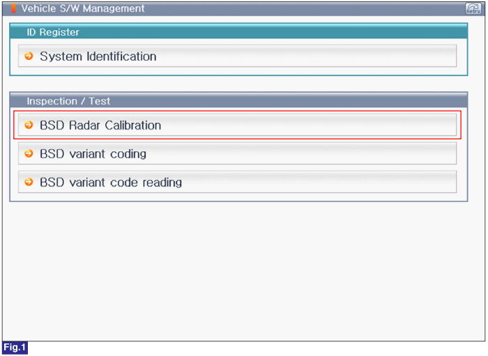
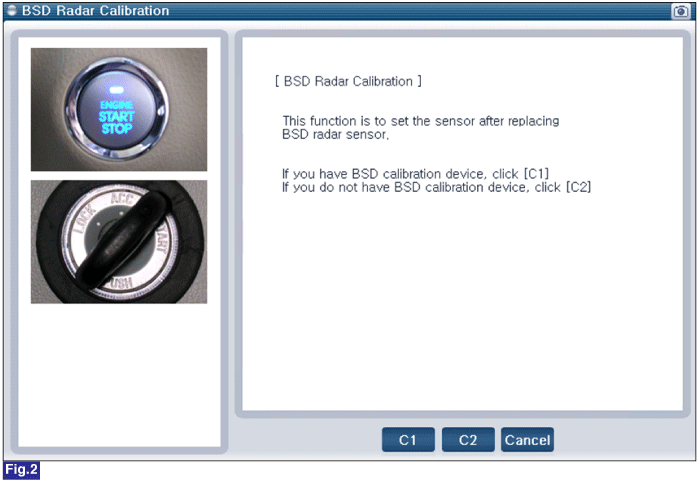

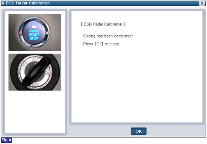
Fig.1) BSD Radar Calibration 1
Fig.2) BSD Radar Calibration 2
Fig.3) BSD Radar Calibration 3
Fig.4) BSD Radar Calibration 4
Connect GDS to Data Link Connector(DLC).
Ignition "ON".
Select "Vehicle S/W Management" with GDS.
Select "BSD Variant Coding" under Inspection / Test.
Refer to following procedure to perform Vehicle S/W Management.
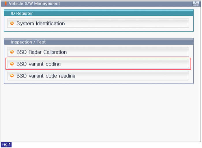

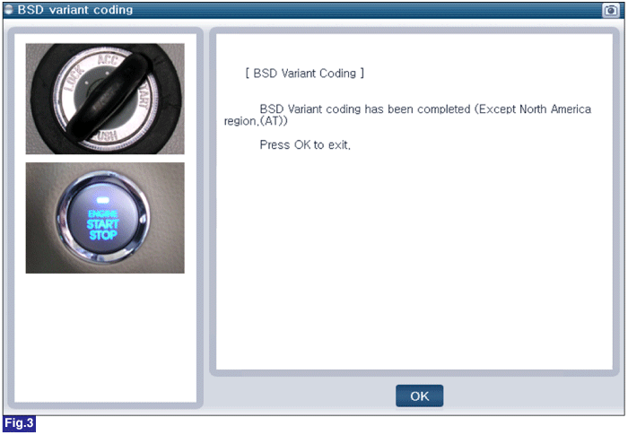
Fig.1) BSD Variant Coding 1
Fig.2) BSD Variant Coding 2
Fig.3) BSD Variant Coding 3
Connect GDS to Data Link Connector(DLC).
Ignition "ON".
Select "Vehicle S/W Management" with GDS.
Select "BSD Variant Code Reading" under Inspection / Test.
Refer to following procedure to perform Vehicle S/W Management.
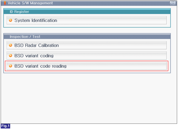
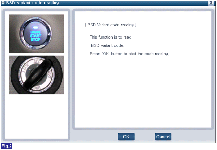
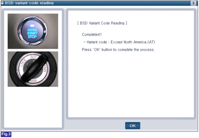
Fig.1) BSD Variant Code Reading 1
Fig.2) BSD Variant Code Reading 2
Fig.3) BSD Variant Code Reading 3
