Has a problem been found?
 | ▶ Repair as necessary and go to "Verification of Vehicle Repair" procedure. |
 | ▶ Go to next procedure. |
Many malfunctions in the electrical system are caused by poor harness and terminals.
Faults can also be caused by interference from other electrical systems, and mechanical or chemical damage.
Thoroughly check connectors for looseness, poor connection, bending, corrosion, contamination, deterioration,or damage.
Has a problem been found?
 | ▶ Repair as necessary and go to "Verification of Vehicle Repair" procedure. |
 | ▶ Go to next procedure. |
Ignition "OFF"
Make sure all control modules' connectors are properly connected.
Measure registance between terminal CAN High and CAN Low of diagnostic connector.
Specification : About 60 Ω
Is the measured registance within specification ?
 | ▶ Check PCM connectors for looseness, poor connection, bending, corrosion, contamination, deterioration, or damage. Repair or replace as necessary and then go to "Verification of Vehicle Repair" procedure. ▶ Go to next procedure. |
 | ▶ In case measure value is out of specification, check for CAN Impedence Resistor and repair or replace as necessary and then go to "Verification of Vehicle Repair" procedure. ▶ If the measured value is lower than 10Ω, repair or replace CAN High and CAN Low are short each other. And then, go to "Verification of Vehicle Repair" procedure. ▶ If the measured value is ∞ , repair or replace the open in CAN High /CAN Low circuit. And then, go to 'Verification of Vehicle Repair" procedure. ▶ Go to next procedure. |
IG KEY OFF.
Disconnect PCM, Instrument Cluster connector.
Measure registance between terminal CAN High and CAN Low of diagnostic connector.
Specification : About 120 Ω
Is the measured value within specification ?
 | ▶ Go to next procedure. |
 | ▶ Substitute with known-good PCM or CLU and check for proper operation. If problem is corrected, replace PCM or CLU and then go to "Verification of Vehicle Repair" procedure. |
IG KEY OFF
Disconnect PCM, TPMS Module, ESP and each Module connector.
IG KEY OFF
Measure voltage between CAN high terminal of diagnostic connector and chassis ground.
Measure voltage between CAN low terminal of diagnostic connector and chassis ground.
Specification : About 0V
IG KEY OFF.
Disconnect PCM, TPMS Module, ESP and each Module connector.
Measure resistance between CAN high terminal of diagnostic connector and chassis ground.
Measure resistance between CAN low terminal of diagnostic connector and chassis ground.
Specification : ∞
Is the measured value within specification ?
 | ▶ Fault is intermittent caused by poor contact in the TPMS module’s connector or was repaired and TPMS module memory was not cleared. Thoroughly check connectors for looseness, poor connection, bending, corrosion, contamination, deterioration, or damage. ▶ Substitute with known-good TPMS Module and check for proper operation. If problem is corrected, replace TPMS Module and then go to "Verification of Vehicle Repair" procedure. ▶ Perfrom "Register Sensor" in "Vehicle S/W Management" with GDS TPMS(Exciter) or drive vehicle with over 25 km/h for 10 minutes to complete auto-learning and auto-location, after TPMS Sensor is replaced. |
 | ▶ Check short to battery in communication line. And then, go to 'Verification of Vehicle Repair" procedure. ▶ Check short to ground in communication line. And then, go to 'Verification of Vehicle Repair" procedure. |
Reference) Write VIN
1. Connect GDS to Data Link Connector(DLC).
2. Ignition "ON"
3. Select "Write VIN" in "Vehicle S/W Management" with GDS.
4. Perform following procedure.
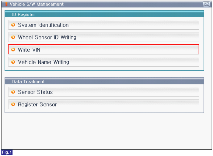
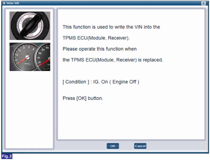
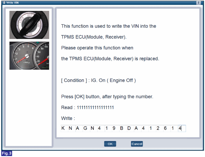
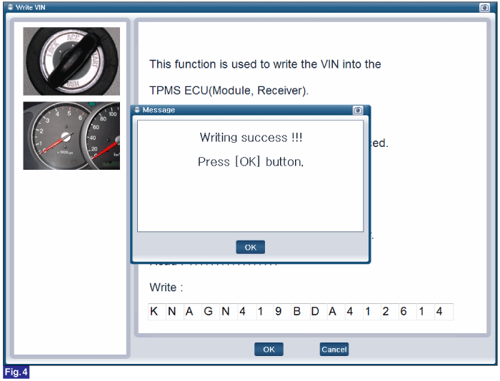
FIG.1) Write VIN1
FIG.2) Write VIN2
FIG.3) Write VIN3
FIG.4) Write VIN4
Reference) Vehicle Name Writing
1. Connect GDS to Data Link Connector(DLC).
2. Ignition "ON"
3. Select "Vehicle Name Writing" in "Vehicle S/W Management" with GDS.
4. Perform following procedure.
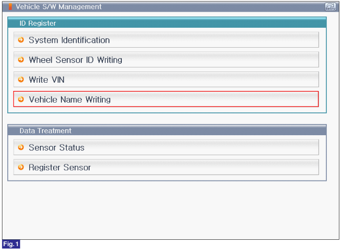
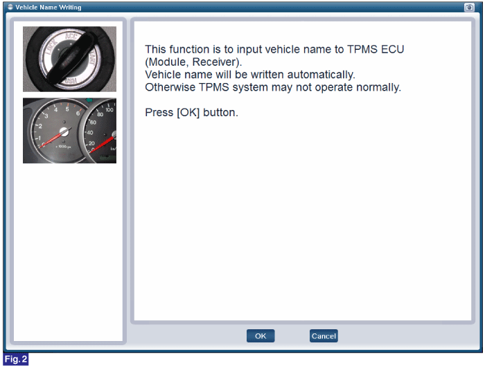
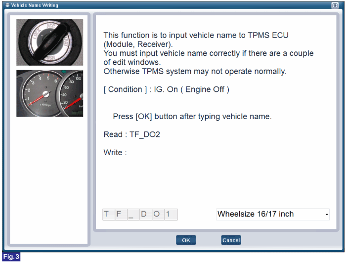
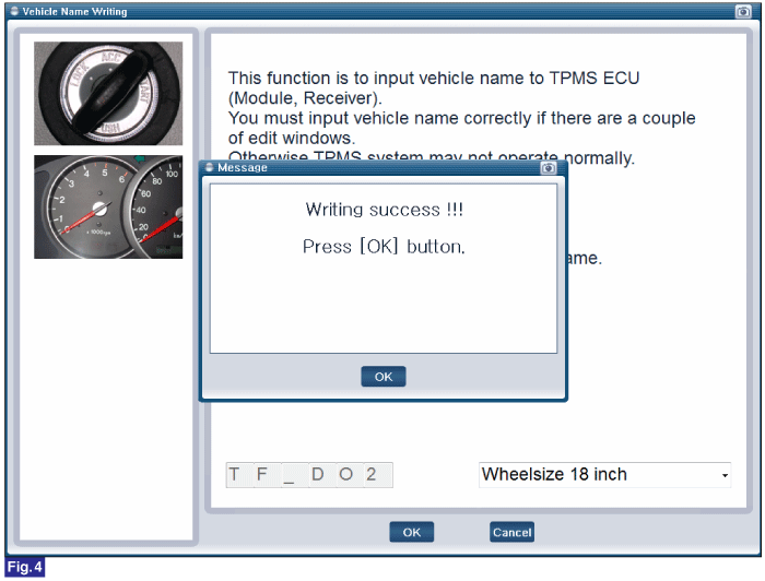
FIG.1) Vehicle Name Writing 1
FIG.2) Vehicle Name Writing 2
FIG.3) Vehicle Name Writing 3
FIG.4) Vehicle Name Writing 4
Reference) Register Sensor
1. Connect GDS to Data Link Connector(DLC).
2. Ignition "ON"
3. Select "Register Sensor" in "Vehicle S/W Management" with GDS.
4. Perform following procedure.
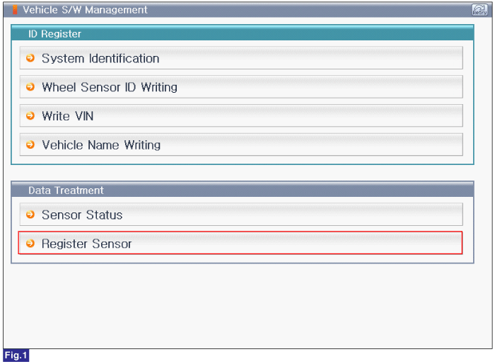
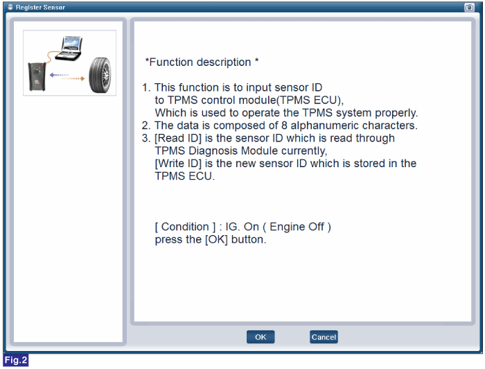
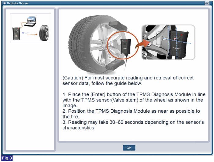
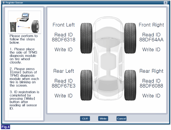
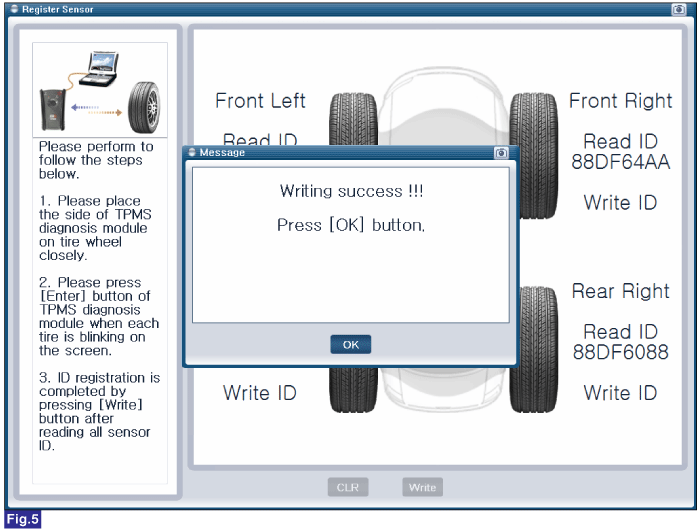
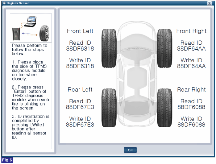
FIG.1) Register Sensor 1
FIG.2) Register Sensor 2
FIG.3) Register Sensor 3
FIG.4) Register Sensor 4
FIG.5) Register Sensor 5
FIG.6) Register Sensor 6