6.
Erase DTC.
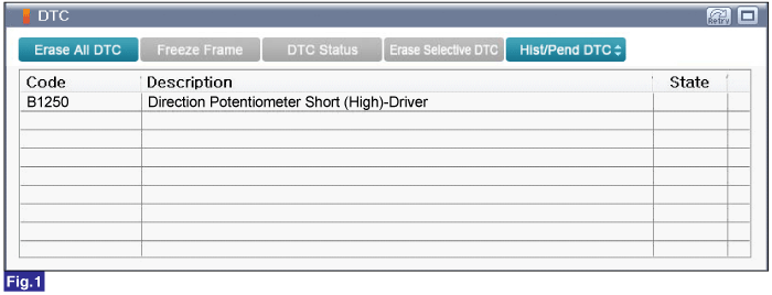
Fig.1) Diagnostic Trouble Code(DTC) is shown above
Ignition "OFF".
Connect GDS to Data Link Connector(DLC).
Ignition "ON", engine "OFF".
Select "Diagnostic Trouble Codes(DTC)" mode.
Check for any DTCs on the "Diagnostic Trouble Code(DTC)" with GDS.
Erase DTC.
Fig.1) Diagnostic Trouble Code(DTC) is shown above
After erase DTC Check for any DTCs again.
Is the same DTC occurred again?
 | ▶ Perform following procedures. |
 | ▶ Fault is intermittent caused by poor contact in the sensor's and, or A/C control module 's connector or was repaired and A/C control module memory was not cleared. Thoroughly check connectors for looseness, poor connection, bending, corrosion, contamination,deterioration, or damage. Repair or replace as necessary and then go to "Verification of Vehicle Repair" procedure. |
Connect GDS with diagnostic connector.
Warm up the engine to normal engine temperature after engine starts.
Select and monitor "Direction Potentiometer-Driver" parameter on the "Current Data" with GDS.
Select and perform "Actuation test" for "Driver Mode Door - Vent / Floor / Defrost" in order".
Monitor parameter value change in accordance with performing each "Acutation Test".
Specification : Vent - About below 10%, Floor : About 50%, Defrost : About 90%.
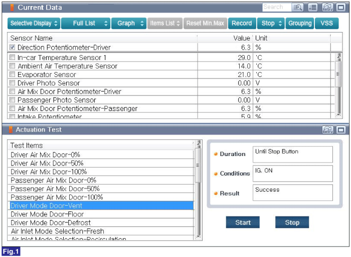
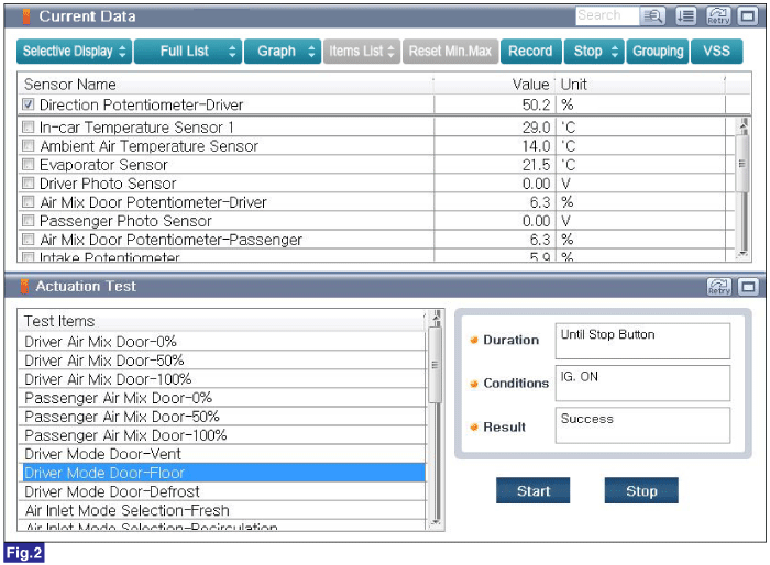
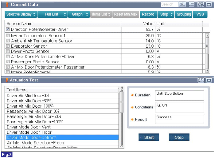
Fig.1) Actuation test for Driver Mode Door - Vent
Fig.2) Actuation test for Driver Mode Door - Floor
Fig.3) Actuation test for Driver Mode Door - Defrost
Is parameter displayed within specification?
| ▶ This may be a intermittent problem caused by poor contact of component or the A/C control module. ▶ Thoroughly check for looseness, poor connection, bent, corrison, contamination, deformation or damage of connector. ▶ Repair or replace as necessary and then, go to "Verification of Vehicle Repair" procedure. |
| ▶ Go to "Wiring Inspection" procedure. |
