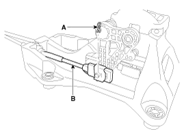
Remove the select cable snap pin (A) and then remove the select cable (B) from the shift lever pin.
Check the select cable for proper operation and for damage.
Check the shift cable for proper operation and for damage.
Check the boots for damage.
Check the boots for wear abrasion sticking, restricted movement or damage.
Remove the following items;
Engine cover.
Air cleaner assembly and air duct.
(Refer to "Intake and Exhaust system" in EM group)
Battery and battery tray.
(Refer to "Charging system" in EE group)
Remove the floor Interior console assembly.
(Refer to "Interior(Console)" in BD group)
Remove the select cable snap pin (A) and then remove the select cable (B) from the shift lever pin.

Remove the clip (A) and then remove the shift cable (B) from the shift lever assembly.
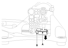
Remove the clip (A) from the shift lever assembly.
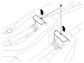
Remove the retainer (A) after removing a nuts (B).
Tightening torque:
8.8 ~13.7 N.m (0.9 ~ 1.4 kgf.m, 6.5 ~10.1 lb-ft)
Remove the SRS Control Module.
(Refer to "SRSCM" in RT group)
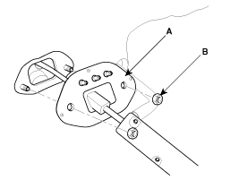
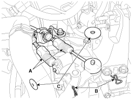
Remove the shift & select cable (A).
Remove the pin (B) and washer (C).
Make unlock clip (D) and then remove the shift & select cable (A) and the clip (D) from the bracket.
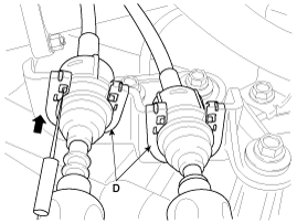
When intalling, do not reuse the clip (D).
Remove the shift cable at cabin room.
Installation is the reverse of removal.
When installing, set room side shift lever and T/M side lever to "Neutral" position.
When install the select cable, adjust the select cable.
(Refer to "Control Cable adjustment procedure" in this group.)
After installing, check to be sure that this part operates as designed at each range of T/M side corresponding to each position of shift lever.
Remove the select cable snap pin (A) and then remove the select cable (B) from the shift lever pin.

Shift the shift lever to 3rd gear.
Move the adjuster (A) in the direction as shown in the illustration.
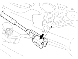
Install the select cable in the shift lever pin.
Press the adjuster (A).
Install the snap pin (B).
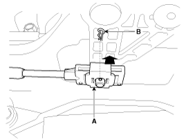
After installing, check to be sure that this part operates as designed at each range of T/M side corresponding to each position of shift lever.