1.
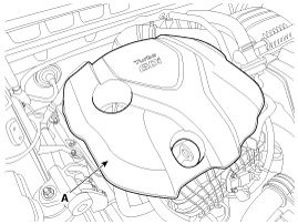
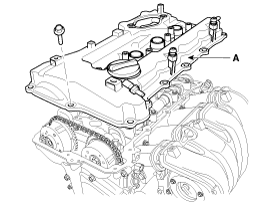
Remove the engine cover (A).
Use fender covers to avoid damaging painted surfaces.
To avoid damage, unplug the wiring connectors carefully while holding the connector portion.
Mark all wiring and hoses to avoid misconnection.
In case of removing the high pressure fuel pump, high pressure fuel pipe, delivery pipe, and injector, there may be injury caused by leakage of the high pressure fuel. So don’t do any repair work right after engine stops.
Remove the engine cover (A).
Disconnect the battery negative terminal (A).
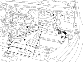
Remove the air duct (B) after removing the mounting bolts.
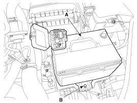
Remove the battery (A) after removing the mounting bracket (B).
Tightening torque:
8.8 ~ 13.7 N.m (0.9 ~ 1.4 kgf.m, 6.5 ~ 10.1 lb-ft)
Remove the air cleaner assembly.
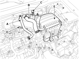
Disconnect the breather hose (A), the recirculation hose (B) and the brake booster vacuum hose (C).
Disconnect the air intake hose (D) and then remove the air cleaner assembly (E).
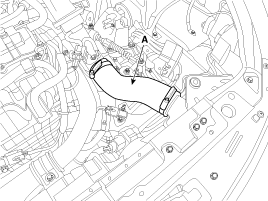
Remove the intercooler inlet hose (A).
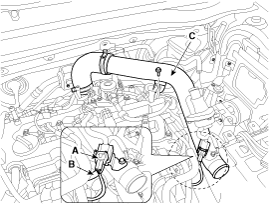
Disconnect the recirculation valve connector (A) and the vacuum hose (B), and then remove the intercooner inlet pipe & hose assembly (C)
Remove the RH front wheel.
Remove the engine room under covers (A,B).
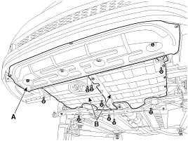
When removing the under cover (B), unfasten the mounting bracket bolts and then remove the under cover and mounting bracket assembly.
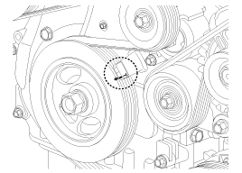
Turn the crankshaft pulley and align its groove with the timing mark of the timing chain cover to set the piston of No.1 cylinder to the top dead center on compression stroke.
Disconnect the exhaust oil control valve connector (A) and the oxygen sensor connector (B).
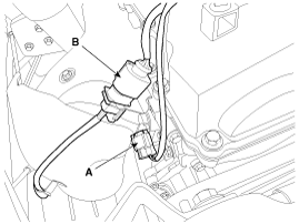
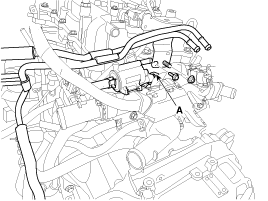
Disconnect the ignition coil connectors (B) and the high pressure fuel pump connector (A), then remove the wiring protector.
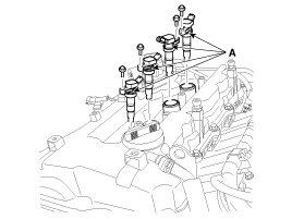
Remove the ignition coils (A).
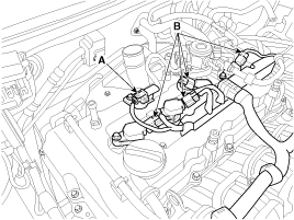
Disconnect the fuel hose (A) and vapor hose (B).
Disconnect PCSV (Purge control solenoid valve) connector (A) and loosen the vacuum pipe assembly mounting bolts and nut.
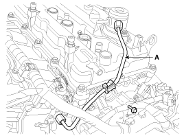
Remove the high pressure pipe (A). (Refer to FL group)
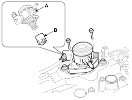
Remove the high pressure fuel pump (A) and the roller tappet (B). (Refer to FL group)
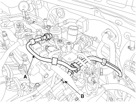
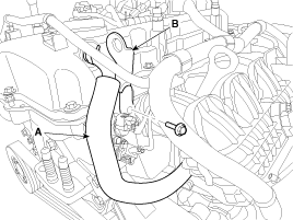
Disconnect the PCV (Positive crankcase ventilation) hose (A), and then remove the front engine hanger (B).
Remove the cylinder head cover (A).
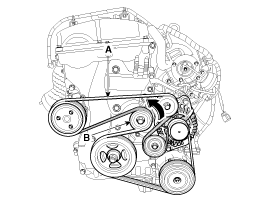
Remove the drive belt (A) after turning the drive belt tensioner (B) counterclockwise.

Remove the A/C compressor lower bolts (A).
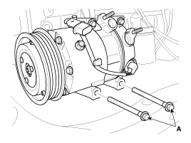
Remove the A/C compressor bracket (A).
Drain the engine oil.
Remove the oil pan (A). Insert the blade of SST (09215-3C000) between the ladder frame and oil pan. Cut off applied sealer and remove the lower oil pan.
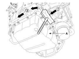
Insert the SST between the oil pan and the ladder frame by tapping it with a plastic hammer in the direction of ① arrow.
After tapping the SST with a plastic hammer along the direction of ② arrow around more than 2/3 edge of the oil pan, remove it from the ladder frame.
Do not turn over the SST abruptly without tapping. It is result in damage of the SST.
Be careful not to damage the contact surfaces of ladder frame and lower oil pan.
Set the jack to the edge of ladder frame.
Put the wooden block between ladder frame and jack.
Be careful not to damage the balance shaft & oil pump module.
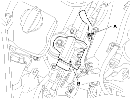
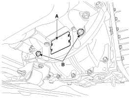
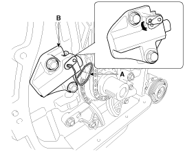
Disconnect the ground line (A), and then remove the engine mounting support bracket (B).
Remove the idler (A), the water pump pulley (B), the crankshaft pulley (C) and the drive belt tensioner pulley (D).
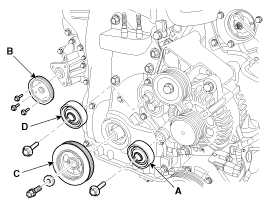
Tensioner pulley bolt is left-handed screw.
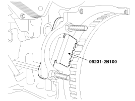
There are two methods to hold the ring gear when installing or removing the crankshaft damper pulley.
Install the SST (09231-2B100) to hold the ring gear after removing the starter.
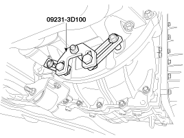
Install the SST (09231-3D100) to hold the ring gear after removing the dust cover.
Remove the dust cover (A) on the bottom of the ladder frame and unfasten the two transaxle mounting bolts (B).
Adjust the length of the holder nuts (A) so that the front plate of the holder (B) puts in the ring gear (C) teeth.
Adjust the angle of the links (D) so that the two transaxle mounting bolts can be fastened to the original mounted holes.
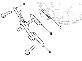
Install the SST (09231-3D100) using the two transaxle mounting bolts and spacers. Tighten the bolts and nuts of the holder and links securely.
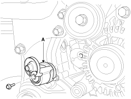
Remove the drive belt tensioner (A).
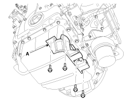
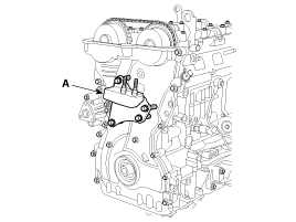
Remove the engine support bracket (A).
Remove the timing chain cover (A) by gently prying the portions between the cylinder head and cylinder block.
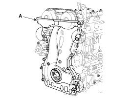
Be careful not to damage the contact surfaces of cylinder block, cylinder head and timing chain cover.
Make sure that the key (A) of crankshaft is aligned with the mating surface of main bearing cap. As a result of this, the piston of No.1 cylinder is placed at the top dead center on compression stroke.
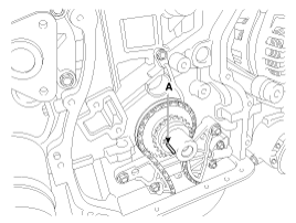
Release the ratchet by pulling the link down using a thin rod. Compress the piston and then insert a stopper pin (A) into the hole on the ratchet to hold the compressed piston. Remove the timing chain tensioner (B).
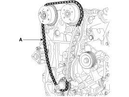
Remove the timing chain tensioner arm (A).
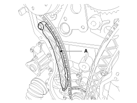
Remove the timing chain (A).
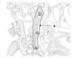
Remove the timing chain guide (A).
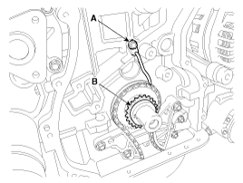
Remove the timing chain oil jet (A) and the crankshaft chain sprocket (B).
Remove the balance shaft chain. (Refer to Lubrication system in this group)
