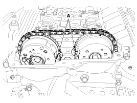
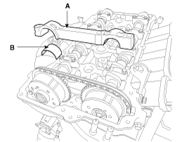
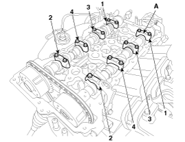
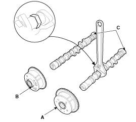
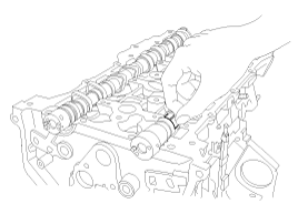
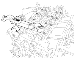
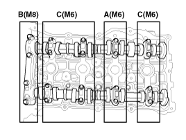
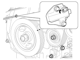
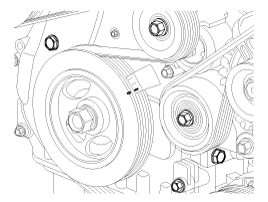
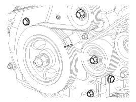
2.
Set No.1 cylinder to TDC/compression.
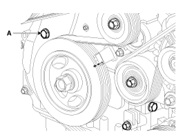
A.
Turn the crankshaft pulley and align its groove with the timing mark "T" of the lower timing chain cover.
B.
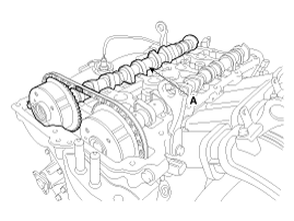
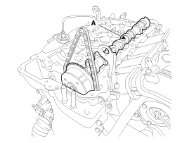
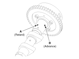
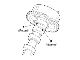
Check that the mark(A) of the CVVT sprockets are in straight line on the cylinder head surface as shown in the illustration.
If not, turn the crankshaft one revolution (360°)