1.
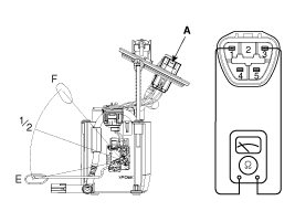
Using an ohmmeter, measure the resistance between terminals 1 and 3 of sender connector (A) at each float level.

Pin No. | discription |
1 | Fuel sender ground |
2 | - |
3 | Fuel sender signal |
4 | - |
Using an ohmmeter, measure the resistance between terminals 1 and 3 of sender connector (A) at each float level.

Pin No. | discription |
1 | Fuel sender ground |
2 | - |
3 | Fuel sender signal |
4 | - |
Also check that the resistance changes smoothly when the float is moved from "E" to "F".
Position | Resistance (Ω) | Capacity (ℓ) |
E | 198 ~ 205 | 5 |
1/2 | 72.7 | 35 |
F | 7 ~ 9 | 67 |