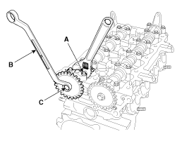
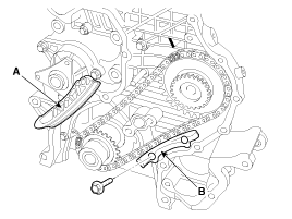
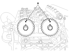
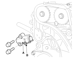
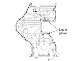
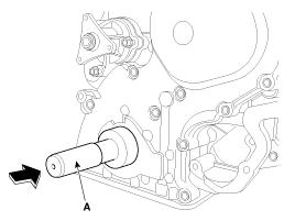
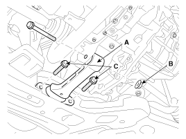
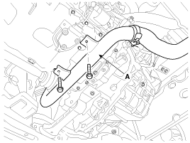
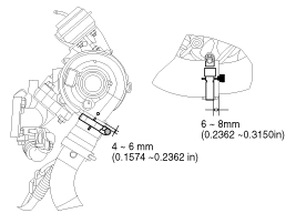
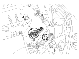
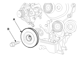
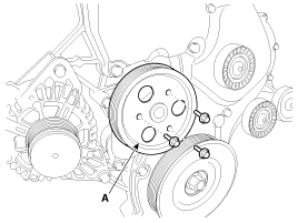
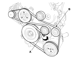
Installation
1.

Install the camshaft sprocket and tighten the bolt to the specified torque.
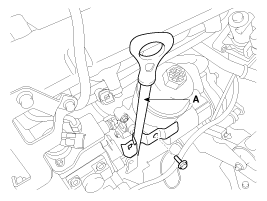
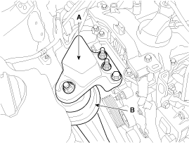
(1)

Temporarily install the camshaft sprocket bolt (C).

(2)

Hold the portion (A) of the camshaft with a hexagonal wrench, and tighten the bolt (C) with a wrench (B).

Tightening torque :

68.6 ~ 73.5N.m (7.0 ~ 7.5kgf.m, 50.6 ~ 54.2lb-ft)

2.

Install the timing chain case (A) with new gasket.

Tightening torque

Bolt (B) :

24.5 ~ 30.4N.m (2.5 ~ 3.1kgf.m, 18.1 ~ 22.4lb-ft)

Bolt (C) :

18.6 ~ 27.5N.m (1.9 ~ 2.8kgf.m, 13.7 ~ 20.3lb-ft)

Bolt (D) :

25.5 ~ 34.3N.m (2.6 ~ 3.5kgf.m, 18.8 ~ 25.3lb-ft)

caution

Be careful not to press gasket protruded from lower face of chain case and bedplate after assembling lower gasket.

3.

Replace the hook of the engine support fixture to the front engine hanger.

(1)

Replace the hook of the engine support fixture to the front engine hanger.

(2)

Remove the jack from the bed plate.

4.

Install the water pump (A).

Tightening torque :

19.6 ~ 24.5N.m (2.0 ~ 2.5kgf.m, 14.5 ~ 18.1lb-ft)

5.

Install the high pressure fuel pump (B, C) and connect the fuel tubes (A).

Tightening torque

Bolts (B) :

14.7 ~ 19.6N.m (1.5 ~ 2.0kgf.m, 10.8 ~ 14.5lb-ft)

Bolts (C) :

19.6 ~ 25.5N.m (2.0 ~ 2.6kgf.m, 14.5 ~ 18.8lb-ft)

6.

Set the key of crankshaft sprocket to be aligned with the timing mark of timing chain case. As a result of this, place the piston on No.1 cylinder at the top dead center on compression stroke.

7.

After install timing chain "A" with high pressure pump sprocket (B) equipped at the crankshaft sprocket (C), and then install high pressure pump sprocket at the high pressure pump shaft.

note

Apply engine oil to radial face (A) of chain case before assembling high pressure pump sprocket.

note

The timing mark of high pressure pump sprocket should be aligned with timing mark on the timing chain case.

The timing mark of each sprocket should be matched with timing mark (color link) of timing chain at installing timing chain as shown below installation.

8.

Pretighten the high pressure fuel pump sprocket nut.

9.

Install timing chain "A" lever (A) and the timing chain guide "1" (B).

Tightening torque :

9.8 ~ 11.8N.m (1.0 ~ 1.2kgf.m, 7.2 ~ 8.7lb-ft)

10.

Install the timing chain "A" auto tensioner (A) and then remove set pin (B).

Tightening torque :

9.8 ~ 11.8N.m (1.0 ~ 1.2kgf.m, 7.2 ~ 8.7lb-ft)

11.

Align the timing mark (A) of camshaft sprocket on the vertical center line of crankshaft.

12.

Install the timing chain "C" (A) as following procedure. High pressure pump sprocket → LH camshaft sprocket → RH camshaft sprocket

note

The timing mark of each sprockets should be matched with timing mark (color link) of timing chain at installing timing chain as shown below illustration.

13.

Install the timing chain guide "2" (A).

Tightening torque :

9.8 ~ 13.7N.m (1.0 ~ 1.4kgf.m, 7.2 ~ 10.1lb-ft)

14.

Install the timing chain "C" lever (A) and the timing chain guide "1" (B).

Tightening torque :

9.8 ~ 11.8N.m (1.0 ~ 1.2kgf.m, 7.2 ~ 8.7lb-ft)

15.

Install the timing chain "C" auto tensioner (A) and then remove set pin (B).

Tightening torque :

9.8 ~ 11.8N.m (1.0 ~ 1.2kgf.m, 7.2 ~ 8.7lb-ft)

16.

Tighten the high pressure pump sprocket nut (A) at specified tightening torque.

Tightening torque :

64.7 ~ 74.5N.m (6.6 ~ 7.6kgf.m, 47.7 ~ 55.0lb-ft)

note

Use the SST(ring gear stopper, 09231-2B100)(A) to tighten the high pressure pump sprocket nut.

17.

Apply liquid gasket evenly to the mating surface of timing chain cover.

note

Standard liquid gasket : LOCTITE 5900, LOCTITE 5900H, THREE BOND 1217H

Check that the mating surfaces are clean and dry before applying liquid gasket.

Assemble the timing chain cover in 5 minutes after applying the liquid gasket.

Apply liquid gasket in a 3mm wide bead without stopping.

18.

Install the timing chain cover (A).

Tightening torque

Bolt (B, C, F) :

19.6 ~ 26.5N.m (2.0 ~ 2.7kgf.m, 14.5 ~ 19.5lb-ft)

Bolt (D, E) :

9.8 ~ 11.8N.m (1.0 ~ 1.2kgf.m, 7.2 ~ 8.7lb-ft)

Bolt (G) :

42.2 ~ 54.0N.m (4.3 ~ 5.5kgf.m, 31.1 ~ 39.8lb-ft)

19.

Install the front oil seal by using SST(09231-2A000, 09231-H1100) (A).

20.

Install the oil strainer (A).

Tightening torque :

Bolts : 19.6 ~ 26.5N.m (2.0 ~ 2.7kgf.m, 14.5 ~ 19.5lb-ft)

Nuts : 9.8 ~ 11.8N.m (1.0 ~ 1.2kgf.m, 7.2 ~ 8.7lb-ft)

21.

Apply liquid gasket evenly to the mating surface of oil pan.

note

Standard liquid gasket : LOCTITE 5900, LOCTITE 5900H, THREE BOND 1217H

Check that the mating surfaces are clean and dry before applying liquid gasket.

Apply liquid gasket in a 3mm wide bead without stopping.Assemble the oil pan in 5 minutes after applying the liquid gasket.

After assembly, wait at least 30 minutes before filling the engine with oil.

caution

Be sure to apply liquid gasket on T-joint of oil pan..

22.

Install the oil pan (A).

Tightening torque :

9.8 ~ 11.8N.m (1.0 ~ 1.2kgf.m, 7.2 ~ 8.7lb-ft)

23.

Install the roll rod bracket (A).

Tightening torque

Nut (B) :

107.9 ~ 127.5N.m (11.0 ~ 13.0kgf.m, 79.6 ~ 94.0lb-ft)

Bolts (C) :

49.0 ~ 63.7N.m (5.0 ~ 6.5kgf.m, 36.1 ~ 47.0lb-ft)

24.

Install the intercooler pipe (A).

Tightening torque :

Clamp : 4.9 ~ 6.9N.m (0.5 ~ 0.7kgf.m, 3.6 ~ 5.1lb-ft)

Bolt : 6.9 ~ 10.8N.m (0.7 ~ 1.1kgf.m, 5.1 ~ 8.0lb-ft)

caution

It is allowed to plaster cleaning liquid or alcohol on the connecting surfaces of hose and pipe, but all kinds of oil is prohibited.

note

The clip wing must be located on the position mark of hose and must not run over it.

note

The groove of hose must be in line with the protrusion of the pipe or turbocharger.

The band must be located on the position mark of hose and must not run over it.

Tighten the torque control cap until it separated. If a torque control cap has already removed, tighten the screw at the specified torque.

25.

Install the A/C compressor. (Refer to A/C compressor in HA group)

26.

Install the timing chain cover plug (B) and the idler (A).

Tightening torque

Idler (A) :

24.5 ~ 34.3N.m (2.5 ~ 3.5kgf.m, 18.2 ~ 25.3lb-ft)

Plug (B) :

25.5 ~ 34.3N.m (2.6 ~ 3.5kgf.m, 18.8 ~ 25.3lb.ft)

27.

Install the crankshaft pulley (A) and crankshaft pulley bolt (B).

Tightening torque :

225.6 ~ 245.2N.m (23.0 ~ 25.0kgf.m, 166.4 ~ 180.8lb-ft)

note

Use the SST(ring gear stopper, 09231-2B100) to Install the crankshaft pulley bolt.

28.

Install the drive belt tensioner (B) and the idler (A).

Tightening torque :

A : 24.5 ~ 34.3N.m (2.5~ 3.5kgf.m, 18.1 ~ 25.3lb-ft)

B : 25.5 ~ 30.4N.m (2.6 ~ 3.1kgf.m, 18.8 ~ 22.4lb-ft)

29.

Install the water pump pulley (A).

Tightening torque :

9.8 ~ 11.8N.m (1.0 ~ 1.2kgf.m, 7.2 ~ 8.7lb-ft)

30.

Install the alternator (A). (Refer to Alternator in EEB group)

Tightening torque :

38.2 ~ 58.8N.m (3.9 ~ 6.0kgf.m, 28.2 ~ 43.4lb-ft)

31.

Install the oil filter&cooler assembly (A) and then install the starter. (Refer to Lubrication system in this group)

Tightening torque :

19.6 ~ 26.5N.m (2.0 ~ 2.7kgf.m, 14.5 ~ 19.5lb-ft)

32.

Install the oil level gauge guide (A).

Tightening torque :

19.6 ~ 26.5N.m (2.0 ~ 2.7kgf.m, 14.5 ~ 19.5lb-ft)

33.

Install the engine mounting support bracket.

(1)

Install the engine mounting insulator (B).

Tightening torque :

49.0 ~ 63.7N.m (5.0 ~ 6.5kgf.m, 36.1 ~ 47.0lb-ft)

(2)

Install the engine mounting support bracket (A).

Tightening torque

Bolts & Nuts :88.3 ~ 107.9N.m (9.0 ~ 11.0kgf.m, 65.1 ~ 79.6lb-ft)

(3)

Remove the engine support fixture and adapter from the engine room.

34.

Install the cylinder head cover (A) with new head cover gasket.

Tighten the cylinder head cover bolts in the sequence shown.

Tightening torque :

1st : 3.9 ~ 5.9N.m (0.4 ~ 0.6kgf.m, 2.9 ~ 4.3lb-ft)

2st : 8.8 ~ 10.8N.m (0.9 ~ 1.1kgf.m, 6.5 ~ 8.0lb-ft)

note

Standard liquid gasket : LOCTITE 5900, LOCTITE 5900H, THREE BOND 1217H

Check that the mating surfaces are clean and dry before applying liquid gasket.

Apply liquid gasket in a 7mm (0.28in) wide bead without stopping.

Assemble the cylinder head cover in 5 minutes after applying the liquid gasket.

After assembly, wait at least 30 minutes before filling the engine with oil.

Apply liquid gasket to T-joint before assembling cylinder head cover.

35.

Install the drive belt (B) after turning the tensioner (A) counterclockwise.

36.

Install the injectors (A), the high pressure pipes (B), the fuel return hose (C) and the turbo charger vacuum hoses (D). (Refer to FL group)

note

Do not reuse the high pressure pipe.

37.

Install the wiring harness protectors and connect the engine wiring harness connectors. (Refer to Engine and transaxle assembly in this group)

38.

Install the under cover and RH side cover.

Tightening torque :

7.8 ~ 11.8N.m (0.8 ~ 1.2kgf.m, 5.8 ~ 8.7lb-ft)

39.

Install the front tires.

40.

Install the air cleaner assembly.(Refer to Engine and transaxle assembly in this group)

41.

Connect the battery negative terminal.

Tightening torque :

3.9 ~ 5.9N.m (0.4 ~ 0.6kgf.m, 3.0 ~ 4.4lb-ft)

Яндекс.Метрика