Has any problems been found?
 | ▶ Repair as necessary and then go to "Verification of Vehicle Repair" procedure. |
 | ▶ Go to next procedure. |
Refer to "Shop Manual" and viasullay and/or physically inspect following conditions;
▶ Vacuum hoses for splits, kinks and improper connections.
▶ Throttle Body Gasket.
▶ Gasket between Intake Manifold and Cylinder head.
▶ Seals between Intake Manifold and Fuel Injectors.
▶ Exhaust system between O2 sensor and the Three way catalyst for air leakage.
▶ Air Cleaner filter element for excessive dirt or for any foreign objects.
▶ Throttle body inlet for damage or for any foreign objects.
▶ Throttle bore and throttle plate for chocking and for any foreign objects.
▶ Restricted exhaust system.
Has any problems been found?
 | ▶ Repair as necessary and then go to "Verification of Vehicle Repair" procedure. |
 | ▶ Go to next procedure. |
Refer to "Shop Manual" and viasullay and/or physically inspect following conditions;
▶ Check EVAP canister for fuel saturation. If the EVAP canister is full of fuel, inspect EVAP and fuel system.
▶ Remove the manifold side vacuum hose from the EVAP canister purge valve.
▶ Using a hand vacuum pump, apply specified vacuum to the manifold side of the valve.
Has any problems been found?
 | ▶ Repair as necessary and then go to "Verification of Vehicle Repair" procedure. |
 | ▶ Go to next procedure. |
Ignition "OFF".
Connect VMI to GDS and set up an oscilloscope as follow (4-channel);
Channel A (+) : Pin No. 3 (V_IP) terminal of Upstream O2 Sensor.
Channel A (-) : Ground
Channel B (+) : Pin No. 1 (Signal) terminal of Downstream O2 Sensor.
Channel B(-) : Ground
Ignition "ON" & Engine "ON".

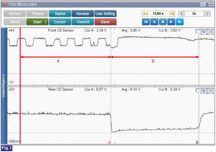
Fig.1) Upstream O2 Sensor and Downstream O2 sensor Signal waveform (Warm-up Condition)
A : Approx. 2500 RPM.
B : Fuel Cut after acceleration.
Is measured value within specficiation?
 | ▶ Go to next procedure. |
 | ▶ Carefully re-do this troubleshooting guide steps. ▶ If no problems were found with the circuits or connectors, Replace the Downstream O2 Sensor and then go to "Verification of Vehicle Repair" procedure. |
Install the component with the specified torques.
Note that internal damage may occur when the component is dropped or mis- treated.
DO NOT use a cleaner, spray, or grease to sensing element and connector of the sensor because oil component in them may cause malfunction or affects on sensor performance.
Sensor and its wiring may be damaged in case of contacting with the exhaust system(Exhaust Manifold, Catalytic Converter, and others).
Ignition "OFF".
Connect VMI to GDS and set up an oscilloscope as follow (2-channel);
Channel A (+) : Pin No. 1 (Signal) terminal of MAP Sensor.
Channel A (-) : Ground
Channel B (+) : Pin No. 4 (TPS1 Signal) terminal of Throttle Body.
Channel B (-) : Ground
Ignition "ON" & Engine "ON".
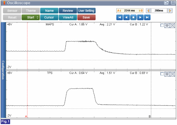
Testing Condition : Idle to Acceleration.
Specification : Refer to Figure below

Fig.1) Normal MAP Sensor and TPS 1 Sensor signal waveform at idle to acceleration.
Is measured value within specification?
 | ▶ Go to next procedure. |
 | ▶ Carefully re-do this troubleshooting guide steps. ▶ If no problems were found with the circuits or connectors, MAP Sensor and then go to "Verification of Vehicle Repair" procedure. |
Install the component with the specified torques.
Note that internal damage may occur when the component is dropped or mis- treated.
Insert the sensor in the installation hole and be careful not to damage.
Refer to "Shop Manual" and release the residual pressure in fuel line.
When removing the fuel pump relay, A Diagnostic Trouble Code(DTC) may occur. Delete the code with the GDS after completion of "Release Residual Pressure in Fuel Line" work.
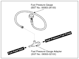
Install the Special Service Tool(SST).
Disconnect the fuel feed tube from the high pressure fuel pump.
There may be some residual pressure even after "Release Residual Pressure in Fuel Line" work. Therefore, cover the hose connection with a shop towel to prevent residual fuel from spilling out before disconnecting any fuel connection.
Install the Special service tool for measuring the fuel pressure in btween the fuel feed tube and the high pressure fuel pump(Refer to figure below).

Inspect fuel leakage on connections among the fuel feed tube, the high pressure fuel pump, and the SST components with Ignition "ON".
Measure Fuel Pressure.
Start the engine and measure the fuel pressure at idle.
Specification : Fuel Pressure - 445 ~ 455 kPa(4.5 ~4.6kgf/cm2 / 64.5~ 66.0 psi)
If the fuel pressure differs from the standard value, repair or replace the related parts(refer to the table below).
Fuel Pressure | Casue | Related Parts |
Too Low | Fuel Filter Clogged | Fuel Filter |
Fuel Leakage | Fuel Pressure Regulator | |
Too High | Fuel Pressure Regulator Stuck | Fuel Pressure Regulator |
Stop the engine, and then check for the change in the fuel pressure gauge reading.
Standard Value : The gauge reading should hold for about 5 minutes after the engine stops
If the gauge reading is not held, repair or replace the related parts(refer to table below).
Fuel Pressure (After Engine Stops) | Casue | Related Parts |
Fuel Pressure Drops Slowly | Leakage on injectors | Injectors |
Fuel Pressure Drops Immediately | Check valve of fuel pump stuck open | Fuel Pump |
Ignition "OFF".
Is fuel pressure value within specification?
 | ▶ Go to "Wiring Inspection" procedure. |
 | ▶ Repair as necessary and then go to "Verification of Vehicle Repair" procedure. |