Ignition "OFF".
Disconnect Battery (-) terminal.
Refer to "Shop Manual" and disconnect Intake OCV connector.
Measure resistance between Pin No. 2 (Power) terminal and Pin No. 1 (Control) terminal of Intake OCV component.
Specification : Approx. 6.9 ~ 7.9Ω at 68℉(20℃)
Is measured value within specification?
![]() | ▶ Go to next procedure. |
![]() | ▶ Carefully re-do this troubleshooting guide steps. ▶ If problem still occurs, replace Intake OCV and then go to "Verification of Vehicle Repair" procedure. |
Install the component with the specified torques.
Note that internal damage may occur when the component is dropped or mis- treated.
Apply engine oil to the valve O-ring before re-installing.
Connect GDS to Data Link Connector(DLC).
Ignition "ON" & Engine "OFF".
Warm up the engine to normal operating temperature.
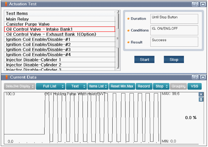
Perform "Oil Control Valve - Intake Bank 1" in "Actuation Test" with GDS.
Monitor "OCV Holding Pulse Width Intake CVVT" parameter in "Current Data" with GDS.
Specification : Refer to Figure below (Also, operating sound(Clicking sound) is heard)
Is the parameter displayed within specification?
![]() | ▶ Go to next procedure. |
![]() | ▶ Carefully re-do this troubleshooting guide steps. ▶ If problem still occurs, replace Intake OCV and then go to "Verification of Vehicle Repair" procedure. |
Install the component with the specified torques.
Note that internal damage may occur when the component is dropped or mis- treated.
Apply engine oil to the valve O-ring before re-installing.
Refer to "Shop Manual" and remove Intake CVVT Assembly.
Check if Intake Cam-phaser is locked.
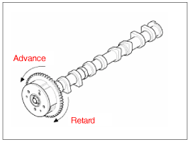
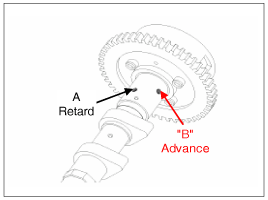
There are 2 oil holes on the cam journal. Upper hole is for advance and the lower hole is for retard.
Apply masking tape to all oil path holes except the advance hole("B") shows in figure below.
To release the CVVT Lock pin, wrap some tape around the tip of an air pressure adapter and apply low air pressure(Approx. 21 psi(1.5 kg/cm2) to the exposed camshaft port. Wrap a shop towel or rag around the CVVT because residual oil may leak out of the unit when applying air pressure.
With low air pressure applied, turn the CVVT to the "Advanced" direction as showed in figure below.
If too much air leaks when applying the low air pressure, the CVVT lock pin may not release and the CVVT may not turn.
Allow the CVVT assembly to move in the "Advance" and "Retard" direction to ensure there is no binding and that it moves freely.
Turn the CVVT by hand and make sure it locks in the maximum "Retard" position.
Does Intake CVVT Assembly operates properly?
![]() | ▶ Go to next procedure. |
![]() | ▶ Carefully re-do this troubleshooting guide steps. ▶ If problem still occurs, replace Intake CVVT Assebmly and then go to "Verification of Vehicle Repair" procedure. |
Connect GDS to Data Link Connector(DLC).
Ignition "ON" & Engine "ON".
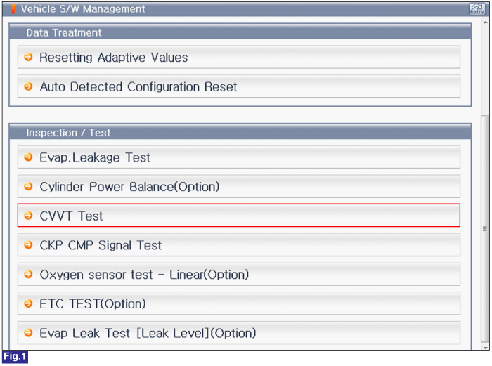
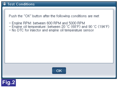
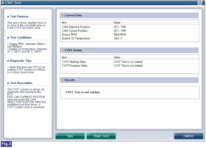
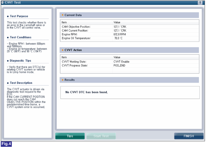
Perform "CVVT Test" in " Vehicle S/W Management" with GDS.
Fig.1) Vehicle S/W Management
Fig.2) Test Condition
Fig.3) CVVT Test 1
Fig.4) CVVT Test 2
Has any DTCs been found?
![]() | ▶ Check the camshaft sprocket and crankshaft sprocket for abnormal wear, cracks, or damange and replace as necessary. ▶ Inspect the tensioner arm and chain guide for abnormal wear, cracks, or damage and replace as necessary. ▶ Check the tensioner piston moves smoothly when the ratchet pawl is released with thin rod. ▶ Perform applicable troubleshooting guide as necessary, and then go to "Verification of Vehicle Repair" procedure. |
![]() | ▶ Carefully re-do this troubleshooting guide steps. ▶ If problem still occurs, replace Intake CVVT Assebmly and then go to "Verification of Vehicle Repair" procedure. |