Ignition "OFF".
Connect VMI to GDS and set up an oscilloscope as follow (2-channel);
Channel A (+) : Pin No. 1 (High) terminal of Fuel Pressure Regulator.
Channel A (-) : Ground
Channel B (+) : Pin No. 2 (Low) terminal of Fuel Pressure Regulator.
Channel B (-) : Ground
Channel Aux : Low Current Sensor to control(high) circuit of Fuel Pressure Regulator.
Ignition "ON" & Engine "ON".
Testing Condition : Idle & Approx. 2500 RPM
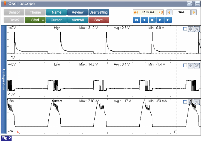
Specification : Current at idle : Approx. 3 A (Average value) / Current at acceleration : Approx. 4.5 A (Average value)
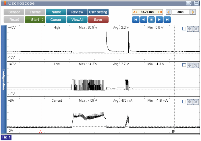
Fig.1) Operating Current of High Pressure Pump(Fuel Pressure Regulator) at Idle. The average operating current value is approximately 3A.
※ The value can be vary by few mA depends on the testing method and environement.
Fig.2) Operating Current of High Pressure Pump(Fuel Pressure Regulator) at Acceleration. The average operating current value is approximately 4,5A.
※ The value can be vary by few mA depends on the testing method and environement.
Is measured value within specification?
![]() | ▶ Go to next procedure. |
![]() | ▶ Carefully re-do this troubleshooting guide steps. ▶ If no problems were found with the circuits or connectors, Replace the Fuel Pressure Regulator and then go to "Verification of Vehicle Repair" procedure. |
In case of removing the high pressure fuel pump, high pressure fuel pipe, and injector, there may be injury caused by leakage of the high pressure fuel. So DONOT perform any repair work right after engine is stopped.
Ignition "OFF".
Connect VMI to GDS and set up an oscilloscope as follow (2-channel);
Channel A (+) : Pin No. 2 (Signal) terminal of Fuel Rail Pressure Sensor.
Channel A (-) : Ground
Channel B (+) : Pin No. 4 (TPS1 Signal) terminal of Throttle Body.
Channel B (-) : Ground
Ignition "ON" & Engine "ON".
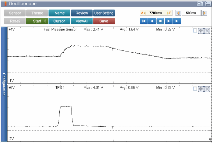
Testing Condition : Idle to Acceleration.
Specification : Signal voltage of fuel rail pressure sensor increases in proportion to engine speed.(Refer to Figure below)
Is the parameter displayed within specification?
![]() | ▶ Carefully re-do this troubleshooting guide steps. ▶ If the diagnostics have been performed correctly with no failure found, replace the PCM, and then go to "Verification of Vehicle Repair" procedure. caution When replacing the PCM, the vehicle equipped with the immobilizer must be performed procedure as below. [In the case of installing used PCM] 1) Perform "PCM Neutral mode" procedure with GDS. (Refer to "Immobilizer" in BE group) 2) After finishing "PCM Neutral mode", perform "Key teaching" procedure with GDS. (Refer to "Immobilizer" in BE group) [In the case of installing new PCM] Perform "Key teaching" procedure with GDS. (Refer to "Immobilizer" in BE group) caution When replacing the PCM, the vehicle equipped with the smart key system (Button start) must be performed procedure as below. [In the case of installing used PCM] 1) Perform "PCM Neutral mode" procedure with GDS. (Refer to "Smart key" in BE group) 2) After finishing "PCM Neutral mode", insert the key (or press the start button) and turn it to the IGN ON and OFF position. Then the PCM learns the smart key information automatically. [In the case of installing new PCM] Insert the key (or press the start button) and turn it to the IGN ON and OFF position. Then the PCM learns the smart key information automatically. |
![]() | ▶ Carefully re-do this troubleshooting guide steps. ▶ If no problems were found with the circuits or connectors, Replace the Fuel Rail Pressure Sensor and then go to "Verification of Vehicle Repair" procedure. caution
–
Install the component with the specified torques.
–
Note that internal damage may occur when the component is dropped or mis- treated. |