
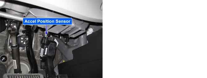
The Electronic Throttle Control(ETC) system is made of the components throttle body, Throttle Position Sensor(TPS) 1&2 and Accelerator Position Sensor(APS)1&2.The APS is mounted in the accelerator pedal to detect the opening angle of the accelerator pedal. It has 2 sensors to detect the accelerator position and a malfunction of the accelerator position sensor. The PCM judges the current opening angle of the accelerator pedal from APS1&2, and the PCM controls the throttle motor based on these signals.
PCM sets DTC P2138 if the PCM detects output voltage of the APS1 is not proportion to APS2.
Item | Detecting Condition | Possible Cause | |
DTC Strategy |
•
Plausibility check | 1. Poor connection or damaged harness 2. APS1 3. APS2 | |
Enable Conditions | Case1 |
•
No relevant failure | |
Case2 |
•
No relevant failure
•
APS1 >1.0V or APS2 >0.55V | ||
Threshold Value | Case1 |
•
One channel of APS is moving and other channel is not reaching threshold | |
Case2 |
•
Ratio error between APS1 & APS2 | ||
Diagnostic Time | Case1 |
•
0.10 Seconds | |
Case2 |
•
0.35 Seconds | ||
Mil On Condition |
•
Immediate | ||
Limp-Home |
•
Forced limited power mode : The PCM limits opening angle of the throttle valve to max. 50% and engine torque to a certain pre-determined value.
•
The PCM selects the current opening angle of the throttle valve from minimum value of APS1 and APS2. | ||