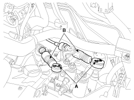
Separate the cable (B) from the control shaft assembly after pin and washer (A).

Remove the following items;
Air cleaner assembly and air duct.
(Refer to"Engine And Transaxle Assembly" in EM group.)
Battery and battery tray.
(Refer to "Charging system" in EE group.)
Separate the cable (B) from the control shaft assembly after pin and washer (A).

Remove the back up lamp switch.
(Refer to "back up lamp switch" in MT group)
Remove the neutral switch.
(Refer to "Neutral switch" in MT group)
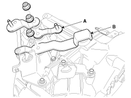
Remove the select lever (A) and shift link assembly (B).
Tightening torque:
42.2 ~ 53.9 N.m (4.3 ~ 5.5 kgf.m, 31.1 ~ 39.8 lb-ft)

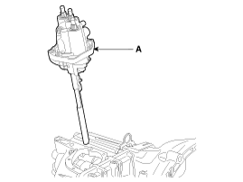
Remove the control shaft assembly (A) after loosen the bolts.
Tightening torque:
9.8 ~ 11.8 N.m (1.0 ~ 1.2 kgf.m, 7.2 ~ 8.7 lb-ft)

Installation is the reverse of removal.
When installing, set control shaft lever to neutral position.
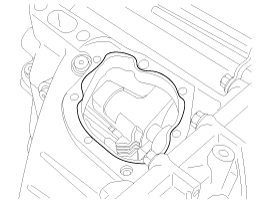
When installing, apply the sealant as shown in the illustration.
Specified sealant : LOCTITE 5060 or Anaerobic adhesives type J (For flange)

After installling, check to be sure that this part operates as designed at each range of T/M side corresponding to each position of shift lever.