Disconnect the brake switch connector (A).
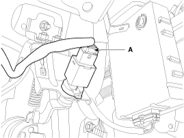
Disconnect the brake switch connector (A).

Pull the locking plate (A) as indicated by the arrow.
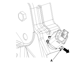
Turn brake switch 45° counterclockwise and remove it.
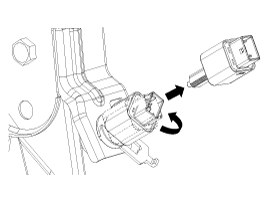
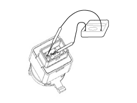
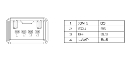
Check the stop lamp switch.
Connect a circuit tester to the connector of stop lamp switch, and check whether or not there is continuity when the plunger of the stop lamp switch is pushed in and when it is released.
The stop lamp switch is in good condition if there is no continuity when plunger is pushed.
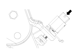
Fix the brake pedal arm and insert fully the brake switch as hiding contact part.
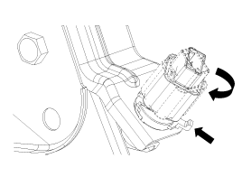
After inserting, turn the brake switch 45° clockwise, and then assemble locking plate by pushing.
Confirm the gap between brake switch and bracket.
Brake clearance (A):
1.0 ~ 2.0 mm (0.04 ~ 0.08 in.)
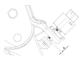
Connect the brake switch connector (A).

If the gap between brake switch and bracket is not 1.0 ~ 2.0mm(0.04~ 0.08in), conform to below.
Disconnect the brake switch connector (B).

Pull the locking plate (A) as indicated by the arrow.

Turn brake switch 45° counterclockwise and remove it.

Fix the brake pedal arm and insert fully the brake switch as hiding contact part.

After inserting, turn the brake switch 45° clockwise, and then assemble locking plate by pushing.

Confirm the gap between brake switch and bracket.
Brake clearance (A):
1.0 ~ 2.0 mm (0.04 ~ 0.08 in.)

Connect the brake switch connector (A).
