

The HO2S(Heated Oxygen Sensor) is used to supply the PCM with information regarding the composition of the air/fuel mixture. The HO2S is positioned in the exhaust pipe ahead of the TWC. To measure the oxygen content, the HO2S requires a supply of ambient air as a reference. Since this is supplied through the wiring, the lead must not be clamped or damaged in any other way. The HO2S produces a voltage that varies between 0.1V and 0.9V under normal operating conditions. The Engine Control Module (PCM) monitors this voltage and determines if the exhaust gas is lean or rich. If the voltage input at the PCM is under approx. 0.45V the exhaust is lean, and if the voltage input is over approx. 0.45V the exhaust is rich. The PCM constantly monitors the HO2S signal during closed loop operation and compensates for a rich or lean condition by decreasing or increasing injector pulse width as necessary.
Signal amplitude plausibility error : In order to determine the signal amplitude plausibility, the PCM monitors front HO2S signal level from rich to lean and from lean to rich. The PCM sets DTC P0134, If the difference of the signal transition level is too small.
Signal plausibility error during fuel cut-off : PCM sets DTC P0134, if the HO2S(B1S1) signal is too high during fuel cut-off period for a predetermined time
Item | Detecting Condition | Possible Cause | |
DTC Strategy | Case1 |
•
Signal plausibility during fuel cut-off |
•
Poor connection or damaged harness
•
HO2S contamination |
Case2 |
•
Signal amplitude plausibility | ||
Enable Conditions | Case1 |
•
fule cut off active
•
Fule cut off phase
•
16g < Integrated Mass Air Flow since Fuel Cut-Off begin
•
No relevant failure
•
10V< Battery voltage | |
Case2 |
•
Signal stroke valid
•
Lambda controller not on the limit
•
Lean / rich cycle time < 2.5 sec
•
No relevant failure
•
10V< Battery voltage | ||
Threshold Value | Case1 |
•
HO2S voltage at fuel-cut mode > 0.1V | |
Case2 |
•
Upstream O2 sensor signal stroke < 0.25 V | ||
Diagnostic Time | Case1 |
•
5 sec. | |
Case2 |
•
120 sec. | ||
MIL On Condition |
•
2 Driving Cycles | ||
Test Condition | GDS Parameter | ||
O2 SNSR VOL.-B1/S1 | O2 SNSR VOL.-B1/S2 | ||
Normal Value when circuit is normal | Idle after warm up | Signal is switching from rich(above 0.45V) to lean(below 0.45V) a minimum of 3 times in 10 seconds. | above 0.7V |
HO2S(B1S1) signal circuit open | Approx. 0.43~0.45V | - | |
HO2S(B1S2) signal circuit open | - | Approx. 0.43~0.45V | |
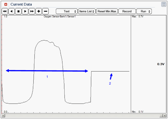
1. Normal value with idle after warm up : Signal is switching from rich(above 0.45V) to lean(below 0.45V) a minimum of 3 times in 10 seconds.
2. GDS display with open in signal circuit : Approx. 0.43~0.45V
