Remove the air duct (A).
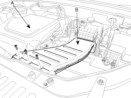
Remove the air duct (A).

Remove the battery.(Refer to 'Battery'in EM group).
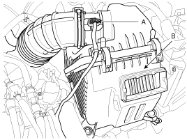
Remove the air cleaner assembly(B) after disconnecting the MAFS connector(A).
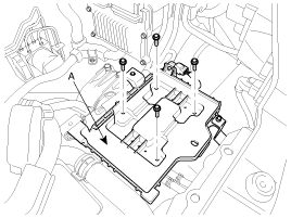
Remove the battery tray (A).
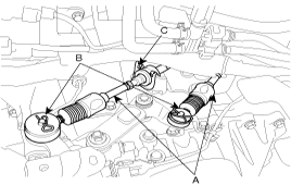
Remove the control cable assembly(A) by removing the snap pins(B) and pushing stoppers facing outside of clips(C).
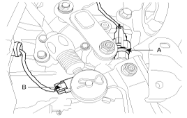
Disconnect the "N" (A) and the "R" (B) position switch.
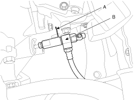
Remove the pin (A) after clamping the concentric sleeve cylinder tube, And then disconnect the tube (B).
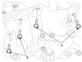
Remove the transaxle upper mounting bolts (A-2ea) and the starter motor mounting bolts (B-2ea).
Tightening torque :
(A) 42.2~54 N.m (4.3~5.5kgf.m, 31.1~39.8 lb-ft)
(B) 49.1~63.8 N.m (5.0~6.5kgf.m, 36.2~47 lb-ft)
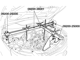
Using the engine support fixture (Support SST No.: 09200-2S000, Beam SST No.: 09200-38001), hold the engine and transaxle assembly safely.
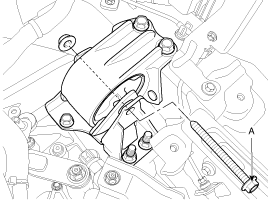
Remove the auto transaxle mounting bracket bolt(A).
Tightening torque :
78.5~107.9N.m (8.0~11.0kgf.m, 57.9~79.6lb-ft)
Remove the front wheels and tires. (Refer to 'Tires/wheels' in SS group)
Remove the steering column joint bolt. (Refer to 'Steering Column and shaft' in ST group)
Keep the neutral-range to prevent the damage of the clock spring inner cable when you handle the steering wheel.
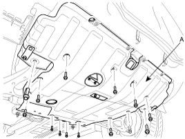
Remove the under cover (A).
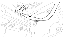
Remove the ground wire (A) from the transaxle case.
Drain power steering oil through the return tube. (Refer to 'Power Steering Oil Pump' in ST group)
Remove the power steering pump bolts. (Refer to 'Power Steering Oil Pump' in ST group)
Drain the transaxle fluid through the drain plug.
Disconnect the lower arm, the tie rod end ball joint, the stabilizer bar link from the front knuckle. (Refer to 'Front Lower Arm' in SS group)
Remove the roll stopper mounting bolts. (Refer to 'Front Stabilizer Bar' in SS group)
Remove the mounting bolts from the sub frame by supporting the sub frame with a jack. (Refer to 'Front Cross Member' in SS group)
Remove the sub frame. (Refer to 'Front Cross Member' in SS group)
Remove the drive shafts from the transaxle. (Refer to 'Front Driveshaft' in DS group)
Remove it with the center shaft after removing the center shaft mounting bolt when removing the right drive shaft.
In case of 4WD, remove the transfer case assembly.(Refer to 'Transfer case' removal).
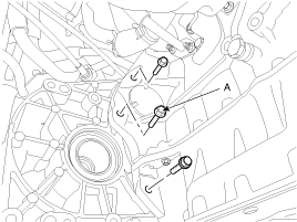
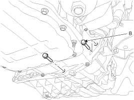
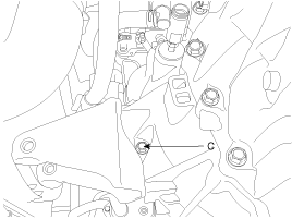
Remove the mounting bolts(A-3ea, B-2ea, C-1ea) of lower part of the transaxle, and the left side cover and remove the transaxle assembly by supporting it with a jack.
Tightening torque :
(A,B,C) 42.2~54N.m (4.3~5.5kgf.m, 31.1~39.8lb-ft)
When removing the transaxle assembly, be careful not to damage any surrounding parts or body components.
Installation is reverse of removal.