Description

Inspect VGT solenoid valve operation and vacuum control by using current data inspection.

Diagnostic Procedure
VGT solenoid valve current data and vacuum inspection.
1.

Connect scantool to Data Link Connector (DLC).

2.

Allow the engine to warm up to normal operating temperature.

3.

Electrical system and A/CON 'OFF'.

4.

Monitor 'Engine speed' and 'VGT actuator' parameters on the scantool.

5.

Measure waveform of terminal '1' of Boost pressure sensor connector by using oscilloscope.(Do not disconnect)

☞ Engine speed : Must keep 770 ± 50 rpm at idle.

☞ VGT actuator : Must keep 92 % at idle.

☞ Boost pressure sensor : Must be approx 1.1V at idle (Measuring by using oscilloscope )

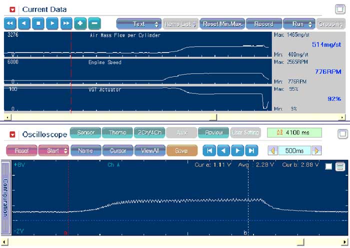
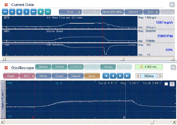
[ Current data at idle ]

6.

Monitor changed data of 'VGT actuator' and 'Boost pressure sensor'

☞ Engine speed : 2,600 ± 100 rpm at stall test.

☞ VGT actuator : Data is decreased to 69% at stall test.

☞ Boost pressure sensor : Must be approx 2.8V at stall test. (Measuring by using oscilloscope)

note

Refer to 'Stall test' of detail inspections (Equipment settings).

[Current data at stall test]

Symptom

Inspection procedure

Case1

● DTC related to VGT system is displayed and poor acceleration occurs. (Electric VGT is stuck.)

● If abnormal feedback signal is outputted by ECM control, DTC is displayed in the electric VGT system.

☞ Refer to DTC guide.

Case2

● 'VGT actuator' is 50% and it is higher than normal data, but 'VGT pressure sensor' voltage is under 2.8V.

● Inspect performance decline in the VGT component (damage of turbine or impeller).

Яндекс.Метрика