1.
Measure the voltage between "Power" terminal of "INJECTOR" harness connector and chassis ground at IG key "ON".
■ Specification : B+
Measure the voltage between "Power" terminal of "INJECTOR" harness connector and chassis ground at IG key "ON".
■ Specification : B+
Is the measured voltage value normal ?
 | ▶ Go to "Injector control circuit inspection" procedure as below. |
 | ▶ Check for open/poor connection/short to ground between "E/R FUSE & RELAY BOX_"SNSR3" fuse and "Power" terminal of "INJECTOR" harness connector. |
Measure the voltage between "Injector Control" terminal of "INJECTOR" harness connector and chassis ground at IG key "ON".
■ Specification : Approx. 3.5 V
Is the measured voltage value normal ?
| ▶ Go to "Injector signal waveform inspection" procedure as below. |
| ▶ Repair open/poor connection/short to ground between "Injector Control" terminal of "INJECTOR" harness connector and "Injector Control" terminal of "ECM/PCM" harness connector. |
Select oscilloscope function on the GDS and connect channel "A" of the VMI to "Injector Control" terminal of "ECM/PCM" harness connector.
Measure the injector signal waveform at IG key "START".
■ Reference signal waveform
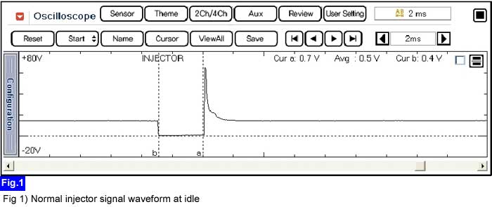
Is the measured injector signal waveform normal ?
| ▶ Click on "Injector" item, and perform "Injector resistance inspection" procedure. |
| ▶ Repair open/poor connection/short to ground between "Injector Control" terminal of "INJECTOR" harness connector and "ECM/PCM" harness connector. |
