1.
Check if "Fuel Pump Relay" current data is normally displayed at IG key "START".
■ Reference current data
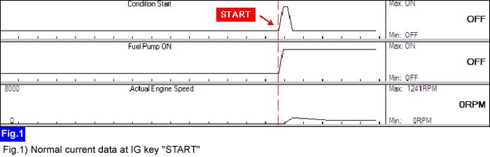
caution
This current data is nothing but an example at certain condition. Thus, the real current data could be different from this example.
Check if "Fuel Pump Relay" current data is normally displayed at IG key "START".
■ Reference current data
This current data is nothing but an example at certain condition. Thus, the real current data could be different from this example.
Is the displayed current data normal?
 | ▶ Go to "Fuel pump relay power circuit inspection" procedure as below. |
 | ▶ Check if the signal is inputted to "ON/START ON" terminal of "ECM/PCM" harness connector. ▶ Go to "Fuel pump relay control circuit inspection" procedure as below. |
Measure the voltage between "FUEL PUMP RELAY_Coil control" terminal on "E/R FUSE & RELAY BOX" and chassis ground at IG key "ON" after removing "FUEL PUMP RELAY" on "E/R FUSE & RELAY BOX".
■ Specification : B+

Is the measured voltage value normal ?
| ▶ Go to "Fuel pump relay control circuit inspection" procedure as below. |
| ▶ Repair open/poor connection between "FUEL PUMP RELAY_Coil control" terminal on "E/R FUSE & RELAY BOX" and "MAIM RELAY_switch" terminal. |
Connect the red tongs of LED circuit tester to battery (+) and the probe of it to "FUEL PUMP RELAY_Coil control" terminal on "E/R FUSE & RELAY BOX".
Perform the actuation test of "Fuel pump relay" by using GDS.
Check LED lamp of the circuit tester while performing the actuation test.
■ Specification : The LED lamp is lit during actuation test.

Is the LED lamp of the circuit tester lit normally ?
| ▶ The fuel pump relay circuit is OK. |
| ▶ Repair open/poor connection between "FUEL PUMP RELAY_Coil control" terminal on "E/R FUSE & RELAY BOX" and "Fuel Pump Relay Control" terminal of "ECM/PCM" harness connector. |
