3.
Measure the resistance between "Power" terminal and "High-voltage" terminal of "IGNITION COIL".[2nd coil resistance]
■ Specification :
1st coil resistance | 0.558 Ω ~ 0.682 Ω (20℃, 68℉) |
2nd coil resistance | 5.95 ㏀ ~ 8.05 ㏀ (20℃, 68℉) |
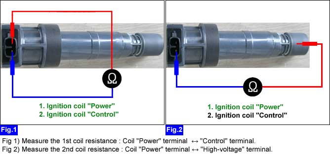
Remove "IGNITION COIL".
Measure the resistance between "Power" terminal and "Control" terminal of "IGNITION COIL".[1st coil resistance]
Measure the resistance between "Power" terminal and "High-voltage" terminal of "IGNITION COIL".[2nd coil resistance]
■ Specification :
1st coil resistance | 0.558 Ω ~ 0.682 Ω (20℃, 68℉) |
2nd coil resistance | 5.95 ㏀ ~ 8.05 ㏀ (20℃, 68℉) |
Are the 1st coil resistance and the 2nd coil resistance normal?
 | ▶ Go to "1st ignition signal waveform inspection" procedure as below. |
 | ▶ Replace the ignition coil. |
Select oscilloscope function on the GDS and connect channel "A" of the VMI to "Ignition Coil Control" terminal of "ECM/PCM" harness connecter.
Measure the signal waveform of the 1st ignition at IG key "START".
■ Reference signal waveform
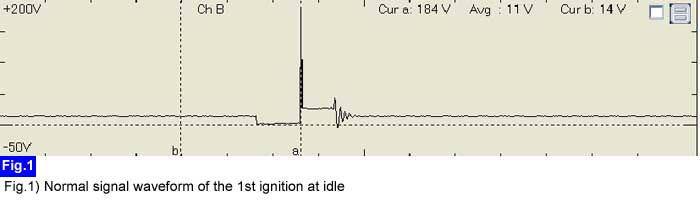
Is the measured 1st ignition signal waveform normal ?
| ▶ Click on "Ignition coil circuit" item for more details. |
| ▶ Replace the ignition coil. |
