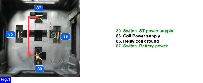
3.
Measure the voltage between "ST" terminal of "START SOLENOID" harness connector and battery (-) terminal.
■ Specification : B+
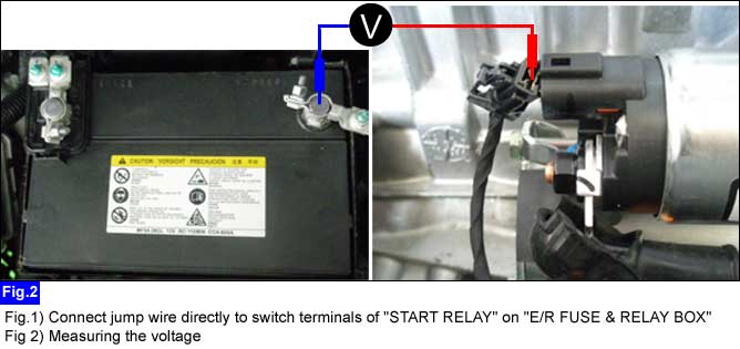
Remove "START RELAY" on "E/R FUSE & RELAY BOX" and disconnect "ST" terminal of "START SOLENOID" harness connector.
Connect jump wire directly to switch terminals of "START RELAY".
Measure the voltage between "ST" terminal of "START SOLENOID" harness connector and battery (-) terminal.
■ Specification : B+
Is the measured voltage value normally ?
 | ▶ Go to "Start relay control circuit inspection" procedure. |
 | ▶ Repair fuse open/poor connection. ▶ Check for open between "IGN2" fuse and "START RELAY_ST power supply" terminal on "E/R FUSE & RELAY BOX". |
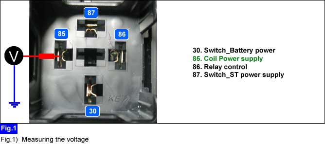
Measure the voltage between "START RELAY_coil power supply" on "E/R FUSE & RELAY BOX" terminal and chassis ground at IG key "START".
■ Specification : B+
Is the measured voltage value normally ?
| ▶ Repair open/poor connection between "START RELAY_coil power supply" terminal on "E/R FUSE & RELAY BOX" and chassis ground. ▶ Repair/replace "START RELAY". ▶ Click on "ST signal" item for more details. ▶ Click on "Immobilizer" item for more details. ▶ Click on "SMK" item for more details. ▶ Click on "PDM" item for more details. |
| ▶ Check "BURGLAR ALARM RELAY". ▶ Repair inhibitor switch(A/T) or ignition lock switch(M/T). ▶ Repair open/poor connection between "START" terminal of "IGNITION SWITCH" and "START RELAY_coil power supply" terminal on "E/R FUSE & RELAY BOX". |
