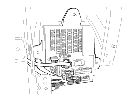
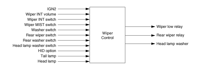
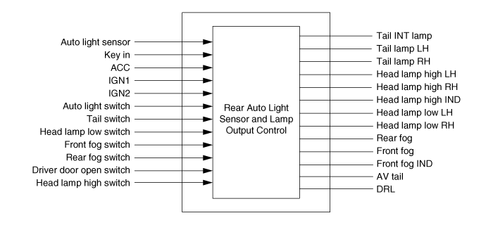
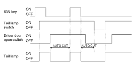
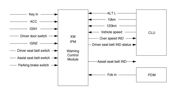
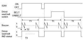
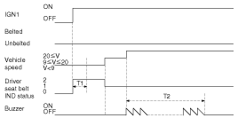
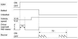
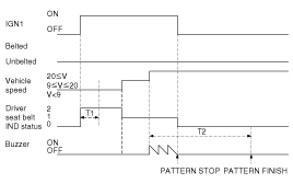
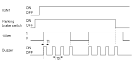
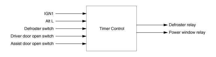
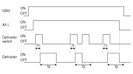
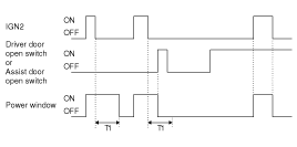
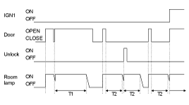
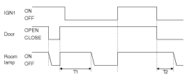
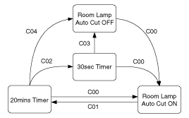
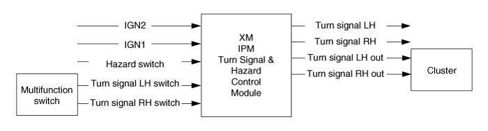
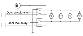
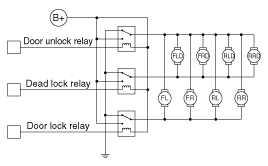
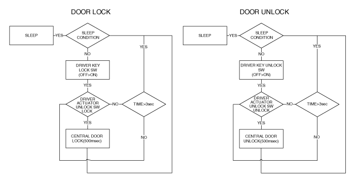
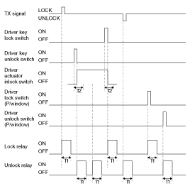
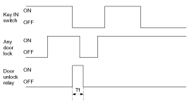
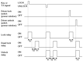
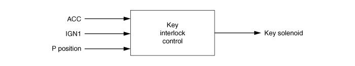
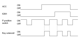
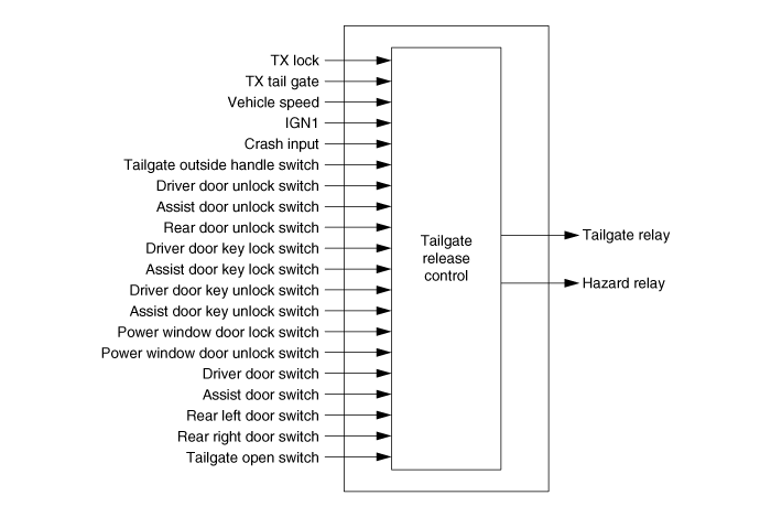
IPM (Intelligent intergrated Platform Module) receives various input switch signals ling time and alarm fuctions for fr washer interlocking wiper, fr intermittent wiper, mist wiper, rear washer interlocking wiper, rear wiper, tail lamp autocut, head lamp low/high, auto light, AV tail, DRL, front/rear fog lamp, IGN key hole illumination, decayed loom lamp, head lamp washer, manual HLLD , seat belt warning/reminder, key operated warning, over speed warning, parking start warning, SMK warning, rear defogger, front deicer, power window timer, rear seat warmer timer, central door lock/unlock, IGN key reminder, passive key reminder, dead lock, crash door unlock, auto door lock/unlock, anti-theft , tailgate release control. | ![]() |
Wiper Data Flow
Wiper control priority
1. Control of washer interlocking wiper
2. MIST wiper control
3. INT wiper control
Control of front washer Interlocking Wiper
Turn Washer switch ON in IGN2 ON and turn Wiper low relay ON after T1.
If Washer switch is input in 0.06~0.2 second, turn OFF Wiper low relay output after T3.
However, Washer switch input during operating washer interlocking wiper is ignored, and received after operating washer interlocking wiper.
T1 : 0.3±0.03sec, T2 : 0.06~0.2sec, T3 : 0.7±0.1sec
T3=0 (if T2 is less than 0.06sec)
Turn Washer switch ON in IGN2 ON and trun ON Wiper low relay out after T1.
If Washer switch Input takes more than 0.2 second, turn ON and OFF Wiper low relay within 2.5∼3.8 seconds after turing Washer switch OFF.
However, Washer switch input is ignored during operating washer interlocking wiper, and received after operating washer interlocking wiper.
T1 : 0.3±0.03sec, T2 : above 0.2sec, T3 : 2.5~3.8sec
If Washer switch is ON for over 0.2 second in operation of INT wiper, turn ON washer interlocking wiper output after T1. If Washer switch is ON for less than 0.2 second, turn ON Wiper low relay Output once.
T1 : 0.3±0.03sec, T2: above 0.2 sec, T3 : 2.5~3.8sec, T4 : INT TIME-0.7sec, T5 : 0.06~0.2sec, T6 : 0.7±0.1sec
When turing on (IGN1 ON & IGN2 OFF), Washer switch signal is ignored.
MIST wiper control
When turning on Wiper Mist SW with L _IGN2 ON, turning ON O_WiperLowRLY output for 700ms.
T1 : Min 60ms, T2: Max 100ms, T3 : 700±100ms
If Wiper Mist switch input lasts for over 700ms, maintain Wiper low relay ON. IF Wiper Mist switch is OFF, turn ON Wiper low relay output for 700ms from it is turned OFF.
T1 : Min 60ms, T2: Max 100ms, T3 : 700±100ms, T4 : 700ms
INT wiper control
Intermittent time of intermittent wiper is controlled dependent on the following conditions.
IGN2 switch ON.
Wiper switch INT.
VOLUME level is input to set the intermittent time.
Rear wiper control
Rear wiper realy is continuously operating when turing Rear wiper switch ON with IGN2 switch ON.
Rear INT wiper control
Rear wiper relay is intermittently operating when turning Rear wiper switch ON with IGN2 switch ON.
Repeat ON mode for 0.7 second and OFF mode for 6 seconds.
T1 : 700±100ms, T2 : 6±0.6ms
Control of rear washer interlocking rear wiper
If Rear washer switch is ON with L_IGN2 SW ON, turn ON Rear wiper relay output after T1.
If Rear washer switch Input is carried on for 0.2~0.6 second, turn OFF Rear wiper relay after T3.
However, Rear washer switch input generated during oprating Rear wiper relay is ignored, and received following the operation of Rear wiper relay.
T1 : 0.3±0.1sec, T2 : 0.2~0.6sec, T3 : 0.7±0.1sec
If T2 is not more the 0.2sec, T3=0
If Rear washer switch is ON with IGN2 switch ON, turn ON Rear wiper relay output after T1.
If Rear washer switch input is continued for more than 0.6, turn ON and OFF Rear wiper relay Output for 2.5∼3.8 seconds after turning Rear washer switch OFF. However Rear washer switch Input during operating Rear wiper relay is ignored and received after the operation of Rear wiper relay.
T1 : 0.3±0.1sec, T2 : 0.6↑sec, T3 : 2.5~3.8sec(3sec)
Rear washer switch Input is igonored during continuous operation of O_Rear wiper relay generated by Rear wiper switch.
The function of Rear washer interlocking Rear wiper is primarily taken, in case that Rear washer switch Input is generated during intermittent operation of Rear wiper relay by Rear wiper switch.
Head lamp washer (HID option)
Refer to the following table for VARIANT of this function.
HID Option | Head lamp washer |
ON | Enable |
OFF | Disable |
If Head lamp washer switch Input is detected with IGN2 ON & Tail lamp ON, Washer is activated for the amount of Head lamp washer number and the duration of Head lamp washer ON time, by operating Head lamp washer.
If Washer switch ON is continued for longer than Washer switch time with IGN2 ON & Head lamp low ON, Washer is activated for the amount of Head lamp washer number and the duration of Head lamp washer ON time, by operating Head lamp washer.
If Washer Request is received during operating Head lamp washer, the Request is ignored.
Under the condition that Washer Request is made during Head lamp washer Inhibit Time, the Request is ignored not with standing Washer Request is received after the operation of Head lamp washer. Once Head lamp washer Output is started, a routine of the Output is completed without being stop not with standing Precondition is not met (Tail lamp OFF or HEAD LAMP LOW OFF). However, the out is discontinued with IGN2 OFF.
T1 : Head Lamp Washer On Time,
T2 : Head Lamp Washer Off Time,
T3 : Head Lamp Washer Ingibit Time
T1 : Head Lamp Washer On Time,
T2 : Head Lamp Washer Off Time,
T3 : Head Lamp Washer Ingibit Time,
T4 : Washer SW Time
T1 : Head Lamp Washer On Time,
T2 : Head Lamp Washer Off Time,
T3 : Head Lamp Washer Ingibit Time,
T4 : Washer SW Time
Exterior lamp control data flow
Tail lamp auto cut
IGN KEY is OUT when turning Tail lamp switch ON following IGN KEY ON and Tail lamp is automatically OFF (auto power off) when turning on ON Driver door open switch.
Tail lamp is automatically OFF (auto power off) when turning ON Driver door open switch with IGN KEY ON, and then IGN KEY OUT.
If turning Tail lamp switch ON and OFF in turns follwing auto power off, Tail lamp is ON and AUTO CUT function is disabled.
If IGN KEY is ON again after auto power off, Tail lamp is ON and AUTO CUT function is disabled.
AUTO CUT mode is maintained when changing BATTERY.
Head lamp low control
If turning Head lamp low switch ON with IGN1 ON, Head lamp low is ON.
If IGN1 is OFF or Head lamp low switch is OFF, Head lamp low is OFF.
If IPM does not work with IGN1 ON, Head lamp low Output should be automatically ON.
Manual HLLD control output
When turning ON Head lamp low output, Manual HLLD Power output is ON.
When turning OFF Head lamp low output, Manual HLLD Power output is OFF.
Head lamp low is applicable t the output by Head lamp low switch ON, Auto light Function, or DRL EUROPE Function’.
Head lamp low signal control
If Head lamp low output is ON by ‘Head lamp low switch ON’ or ‘Auto light function’, Head lamp low control output is ON.
If Head lamp low output is ON by ‘DRL EUROPE function’, Head lamp low control output is Off.
If Head lamp low output is turned ON → Off, Head lamp low control output is Off.
Head lamp high control
Head lamp high Input and Head lamp Passing Input by M/F are controlled by single input of Head lamp high switch.
Head lamp high Input
Determined by Head lamp high Input when Head lamp high switch ON with Head lamp low control output ON by IPM, and IGN2 ON.
Head lamp Passing Input
Determined by Head lamp passing Input when Head lamp high switch ON with Head lamp Low control Output OFF and IGN2 ON.
If Head lamp high Input is ON with IGN2 ON, Head lamp high output is ON.
If Head lamp passing is ON with IGN2 ON, Head lamp high output is ON.
Auto light control
Auto light function is not applicable for Europe DRL option (DRL option=GND).
If Auto light power is less than 4V or more than 6V with IGN1 ON & IGN2 ON, it is considered to be malfunctioning. In this case, Head lamp LOW is ON with Auto light switch ON no matter what the value of Auto light sensor is. Filtering time of failing and recovering supply power takes 300msec each.
If Auto light sensor value is adaptable with the condition of Auto light Control, turn light ON immediately.
If Auto light sensor value is equal to the Input value of light ON with IGN1 ON & IGN2 ON, Auto light switch ON, and light OFF, turn light ON after T1: 2.5 ± 0.2sec.
If Auto light sensor value is equal to the Input value of light OFF with light ON, turn light OFF after T2: 2.5 ± 0.2sec.
When turning OFF Auto light switch, immediately turn OFF light.
Auto light sensor value for light ON is as following.
| TAIL LAMP | HEAD LAMP LOW |
ON | 2.5±0.05V | |
OFF | 4.0±0.05V |
TIME CHART based on Filtering time and sensor value in each application region is as following.
T1 : 2.5±0.2s, T2: 2.5±0.2s
Tail interlocking AV control
Tail Interlocking AV control fuction is not applied to Europe DRL option.
If Auto light power is less than 4V or over 6V with ACC ON, it is considered to be malfunctioning. AV Tail Output should be OFF in malfunctioning.
Power supply Filtering time of failing and recovering takes 300msec each.
If Auto light sensor value is equal to the input value of Tail lamp ON with ACC ON, turn ON AV Tail Output after 2.5 ± 0.2 sec.
If Auto light sensor value is equal to the input value of Tail lamp OFF with AV Tail Output ON, turn OFF AV Tail output after 2.5 ± 0.2sec.
Auto light sensor value of light ON is as follows.
| AV Tail |
ON | 2.5±0.05V |
OFF | 4.0±0.05V |
T1 : 2.5±0.2s, T2: 2.5±0.2s
Day time running light
DRL (DAYTIME RUNNING LIGHT) option is categorized into 2 types, based on DRL option Input.
① NON-DRL OPTION: DRL option is not connected. (Switch Open)
② DRL OPTION: DRL option is connected for having ground. (Switch Short To GND)
DRL option is input on a regular basis, and to be based on availability of immediated function.
If IGN2 & Alt L is ON, Tail lamp EXT and Head lamp low is ON.
If Tail lamp switch is ON during DRL functioning, the function of DRL is cancelled.
(Tail lamp output (EXT & INT) is ON and Head lamp low output is OFF.)
Front fog lamp
If turing ON front fog lamp switch with tai lamp ON, turn ON front fog lamp.
If turning OFF front fog lamp switch with front fog lamp ON, turn OFF front fog lamp. (Front fog lamp switch is Lock type Switch)
For DR EUROPE specification, front fog lamp is not ON if front fog lamp switch is ON during DRL operation. (The use of front fog lamp is prohibited)
ST (Cranking): front fog lamp output is OFF with IGN1 ON & IGN2 OFF & ACC OFF not with standing turning on or off front fog lamp switch.
Rear fog lamp
When rear fog lamp switch is OFF and then turned ON with front fog lamp ON after turning ON Tail lamp, and A IGN1 ON, turn ON rear fog lamp.
When rear fog lamp switch is OFF and then turned ON with rear fog lamp ON, trun OFF rear fog lamp.(Self-return type of rear fog lamp switch is in operation)
For ‘DRL EUROPE specification’, rear fog lamp is not ON; when rear fog lamp switch is OFF → ON in DRL operation. (The use of rear fog lamp is prohibited)
When ST (Cranking) condition: IGN1 ON & IGN2 OFF & ACC OFF during rear fog lamp Output (ON) with Head lamp low ON or front fog lamp ON, the Output is stop, and is re-activated only if IGN1 ON & IGN2 ON. (In case of Cranking, and IDLING following saving the revious output condition, the output condition is restored.)
When front fog lamp relay is ON, and front fog switch is ON → OFF after rear fog lamp relay is ON with head lamp relay ON, rear fog lamp relay is OFF.
Priority
Priority | Internal Buzzer Warning | Logic | Load Control |
1 | Rear PAS Warning | IPM | IPM |
2 | Seat Belt Warning | ||
3 | Over Speed Warning | ||
4 | Key Operated Warning | ||
5 | Parking Brake Warning | ||
6 | Steering Column Not Locked Warning (SMK Option) | SMK | |
7 | ID Out Warning | ||
8 | Steering Column Not Unlocked Warning (SMK Option) | ||
9 | SSB Button Warning (SMK Option) | ||
10 | Rheostat Detent Sound | CLU |
Warning control data flow
Seat belt warning timer (General, Middle East, and China)
State | Description |
Initial Condition | IGN1 OFF |
Transition Condition | Driver side seat belt is belted and IGN1=ON |
Action | • Start 6 seconds Driver indicator blinking • The automaton state is changed to IGN1 ON Driver belted |
State | Description |
Initial Condition | IGN1 OFF |
Transition Condition | Driver side seat belt is unbelted and IGN1=ON |
Action | • Start 6 seconds Driver indicator blinking • Start 6 seconds buzzer warning • The automaton state is changed to IGN1 ON Driver unbelted |
State | Description |
Initial Condition | IGN1 ON Driver belted |
Transition Condition | IGN1=OFF |
Action | • Stop 6 seconds Driver indicator blinking • Stop 6 seconds buzzer warning • The automaton state is changed to IGN1 OFF |
State | Description |
Initial Condition | IGN1 ON Driver belted |
Transition Condition | Driver side seat belt is unbelted |
Action | • Start 6 seconds Driver indicator blinking • Start 6 seconds buzzer warning • The automaton state is changed to IGN1 ON Driver unbelted |
State | Description |
Initial Condition | IGN1 ON Driver unbelted |
Transition Condition | IGN1=OFF |
Action | • Stop 6 seconds Driver indicator blinking • Stop 6 seconds buzzer warning • The automaton state is changed to IGN1 OFF |
State | Description |
Initial Condition | IGN1 ON Driver unbelted |
Transition Condition | Driver side seat belt is belted |
Action | • Stop 6 seconds buzzer warning • The automaton state is changed to IGN1 ON DRIVER BELTED |
T1 : 6±1sec, T2 : 1±0.1sec, T3 : 0.6±0.1sec
Seat belt reminder (Europe/Australia)
The SBR (Seat Belt Reminder) includes the following features:
SBR Indicator warning
SBR Buzzer warning
This functional descripotion will be applied to both Driver and Assist SBR.
Basic warning mode
Indicator blinking mode: indicator “ON” for 0.5 second/ ”OFF” for 0.5 second
Buzzer mode: decremental sound (1Hz)
Indicator Blinking & Buzzer sound will be synchronized.
Pattern “START” condition.
UNBELT & [ (V < 20KPH) → (V >= 20KPH) ]
T1 : 6sec, T2 : 100sec, T3 : 1sec, T4 : 0.5sec
(V >= 20KPH) & (BELT → UNBELT)
T1 : 6sec, T2 : 100sec
Pattern “STOP” condition
IGN1 OFF
T1 : 6sec, T2 : 100sec
UNBELT → BELT
T1 : 6sec, T2 : 100sec
Pattern Finished – After pattern finished, state cannot be activated for V(0 ↔ 100kph)
T1 : 6sec, T2 : 100sec
Key operated warning (except EUROPE & AUSTRALIA)
Buzzer is continuously ON in 0.6 second cycle, when key in & Driver door open switch is ON.
Turn off the Buzzer if IGN1 switch is ON or Driver door open switch is OFF or KEY OFF during the output condition.
T1 : 0.6±0.1sec
Over speed warning (MIDDLE EAST)
If [120km = 1] with IGN1 ON, turn ON Over Speed Warning IND, and activate [OverSpeedIND = 1] mode and the BUZZER.
If Over speed is On, immediate warning is started without Filtering Time.
[Over speed IND = 1] mode is maintained to 120km = 0 or IGN1 OFF, and the BUZZER is alarming for 5 seconds.
T1 : 6sec
Parking start warning
If [10km = 1] with IGN1 ON and Parking brake switch ON , Buzzer output.
If [10km = 1] with Parking brake switch ON, turn ON the Buzzer output.
If IGN1 OFF, Parking brake switch OFF or [10km = OFF], turn OFF the Buzzer output.
T1 : 0.3±0.1sec, T2 : 0.7±0.1sec
SMK warning
Refer to Smart key system in this group.
Timer Control data flow
Defroster timer
If turning ON Alt L and then Defroster switch with IGN1 switch ON, turn ON Defroster for 20 minutes. (operated in ENGINE RUNNING Condition)
If Defroster switch is ON during Defroster ON, turn OFF Defroster.
If Alt L OFF or IGN1 OFF during Defroster ON, turn OFF Defroster.
Defroster is not activated with Alt L ON as well as Defroster switch being pushed simultanesouly.
T1 : 60±20msec, T2 : 20±1min
Power window timer
Turn ON Power window if IGN2 switch ON.
Power window output is maintained for 30 seconds and OFF if IGN2 switch is OFF.
The output is immediately OFF if Driver door open switch ON or Assist door open switch ON in the (2) above.
If IGN2 is OFF with Driver door open switch ON or Assist door open switch ON, Power window is OFF.
T1 : 30±1sec
If driver door open switch ON or assist door open switch ON with IGN1 OFF , turn ON key hole illumination.
In case of driver door open switch OFF or assist door open switch OFF with the condition (1) above, turn ON key hole illumination for 30 seconds, and then OFF the lighting.
Turn OFF key hole illumination on activating IGN1 switchin case of (1) and (2) above. However, key hole illumination light should be immediately OFF if ARM WAIT or ARM or ALARM or REARM activation.
T1 : 30±1sec
Room lamp OFF
State | Description |
Initial Condition | Room lamp OFF and doorCLOSED |
Transition Condition | TX UNLOCK Key out event |
Action | Room lamp ON for 30s state activated Room lamp ON for 30 ± 3 seconds |
State | Description |
Initial Condition | Room lamp OFF |
Transition Condition | Door OPEN for over 0.1 second with all doors CLOSED |
Action | Room lamp ON for 20 min state activated Room lamp ON for 20 ± 1 minutes |
State | Description |
Initial Condition | Room lamp OFF and IGN1=OFF |
Transition Condition | IGN1 = ON and door OPEN for over 0.1 seconed |
Action | Room lamp ON state activated Room lamp ON |
T1 : 20±1min, T2 : 30±3sec
Room lamp ON for 30s
State | Description |
Initial Condition | Room lamp ON for 30s and IGN1=OFF |
Transition Condition | Door OPEN for over 0.1 second with all doors CLOSED |
Action | Room lamp ON for 20min state activated Room lamp ON for 20 ± 1 minutes |
State | Description |
Initial Condition | Room lamp ON for 30s and IGN1=OFF |
Transition Condition | TX UNLOCK Key out event |
Action | Maintaining Room lamp ON for 30s Room lamp ON for 30 seconds |
State | Description |
Initial Condition | Room lamp ON for 30s and IGN1=OFF |
Transition Condition | In case of IGN1=ON, after 30 seconds, on ARM being activated, or when all doors are LOCKED |
Action | Room lamp DECAYING state activated Turning OFF Room lamp after diminishing the light for 2 ± 0.2 seconds |
T1 : 20±1min, T2 : 30±3sec
Room lamp ON for 20min
State | Description |
Initial Condition | Room lamp ON for 20min and IGN1=OFF |
Transition Condition | IGN1 = ON |
Action | Room lamp ON state activated Room lamp ON |
State | Description |
Initial Condition | Room lamp ON for 20min and IGN1=OFF |
Transition Condition | In case of doorCLOSE and when all doors are LOCKED, or after 20 minutes |
Action | Room lamp DECAYING state activated Turning OFF Room lamp after diminishing the light for 2 ± 0.2 seconds |
State | Description |
Initial Condition | Room lamp ON for 20min and IGN1=OFF |
Transition Condition | Door CLOSE |
Action | Room lamp ON for 30s state activated Room lamp ON for 30 ± 3 seconds |
T1 : 20±1min, T2 : 30±3sec
Room lamp decaying
State | Description |
Initial Condition | Room lamp DECAYING and IGN1=OFF |
Transition Condition | Door OPEN for over 0.1 second with all doors CLOSE |
Action | Room lamp ON for 20min state activated Room lamp ON for 20 ± 1 minutes |
State | Description |
Initial Condition | Room lamp DECAYING and IGN1=OFF and door CLOSE |
Transition Condition | TX UNLOCK Key out event |
Action | Room lamp ON for 30s state activated Room lamp ON for 30 ± 3 seconds |
State | Description |
Initial Condition | Room lamp DECAYING |
Transition Condition | After the lamp decaying |
Action | Room lamp OFF state activated Room lamp OFF |
State | Description |
Initial Condition | Room lamp DECAYING |
Transition Condition | IGN1 = ON and door OPEN for over 0.1 second |
Action | Room lamp ON state activated Room lamp ON |
T1 : 20±1min, T2 : 30±3sec
Room lamp ON
State | Description |
Initial Condition | Room lamp ON and IGN1=ON and door OPEN |
Transition Condition | Door CLOSE |
Action | Room lamp DECAYING state activated Turning OFF Room lamp after diminishing the light for 2 ± 0.2 seconds |
State | Description |
Initial Condition | Room lamp ON and IGN1=ON and door OPEN |
Transition Condition | IGN1=OFF |
Action | Room lamp ON for 20min state activated Room lamp ON for 20 ± 1 minutes |
State | Description |
Initial Condition | Room lamp ON and IGN1=ON and door OPEN |
Transition Condition | Door CLOSE and IGN1=OFF |
Action | Room lamp ON for 30s state activated Room lamp ON for 30 ± 3 seconds |
T1 : 20±1min, T2 : 30±3sec
Room lamp auto cut
C00: If (ACC=ON or IGN1=ON or IGN2=ON) or (Burglar Alarm state = 1→0) then Room lamp auto cut = ON and 20mins timer stop and 3sec timer stop.
C01: If (Key In = ON or KEY OFF) then start 20mins timer.
C02: If (Burglar alarm = 0→1) then start 3sec timer.
C03: If 3sec timer elapsed then room lamp auto cut = OFF.
C04: If 20mins timer elapsed then room lamp auto cut = OFF.
C05: If (ACC=ON or IGN1=ON or IGN2=ON) or (Burglar Alarm state = 1→0) or (Any door close → open or Tailgate open switch=ON then room lamp auto cut = ON and 20mins timer stop and 3sec timer stop.
Turn signal and hazard control data flow
Flasher function priority
If conditions of activating flashing conflict with each other, functional priorities are as following:
1st : Arm / Disarm / Flashing (Burglar Alarm system) & Tailgate release Flashing
2nd : Burglar Alarm Flashing
3rd : Panic (including MTS) Flashing
4th : Hazard Flashing
5th : Turn Signal Flashing
Turn Left/ Right signal flashing function
If the Left (or Right) turn switch is active and if IGN2 is On, the left (or Right) turn signal outputs are driven. The turn signal is active as long as both conditions ((Turn Signal LH switch or L_Turn Signal RH switch = On) and IGN2 = On) are true and is turned Off when one of these conditions is no longer detected.
If a failure is detected (Bulb/LED) outage or open load on the activated turn signal side, the flasher frequency is doubled.
This failure can be detected when IGN1 and IGN2 On (IGN1 = On and IGN2 = On).
While turn switch is ON and failure was detected, even if bulb (or LED) failure is no longer detected, keep the double blinking flashing and after next turn switch ON transition, only then, flasher is activated with normal blinking.
Lane change turn Left/ Right signal control function
Flasher lane-change feature means that a momentary activation of the turn switch will cause 3 flashes on the indicator circuit.
This lane-change feature operates under the following conditions:
Lane change mode enabled (Lane Enable = ON)
Ignition 2 shall be On, the lane change feature is not available if Ignition 2 is Off.
The "bulb-fail" mode is not working and the flashing frequency is always normal blinking in lane change mode (85 ±10 period/min).
During the lane change mode operation, if the user moves the turn switch in the other direction, then lane change mode is finished and the other direction’s flashing (normal or lane change flashing) will start depending on the switch detection time.
Hazard flashing function
Activating the hazard switch generates the hazard signal, regardless of the Ignition key position. The hazard signal is a permanent sequence. It goes off when the hazard switch is deactivated. The hazard drives both the Left and Right flashing sides.
Like the turn signal flashing, if bulb(or LED) failure is detected, flashing frequency is doubled. But it is ONly possible in IGN1 and IGN2 ON (IGN1 = ON and IGN2 = ON).
Turn signal and hazard priority
Hazard flashing has a higher priority than turn Left/Right control.
During hazard flashing, if turn Flashing is requested, keep the hazard operation.
During turn flashing, if hazard flashing is requested, interrupt the turn flashing and start hazard operation immediately.
During hazard operation if hazard and turn switch are On at the same time, if hazard switch is turned Off, turn flashing starts to operate but, does not discontinue the running period.
Double blinking detection condition
In case of activation of hazard the fault detection will be able to detect the failure only if 3 bulbs of Front or Rear are broken-down.
In case of turn signal activation when one of the front or rear is broken-down (Lamp failure), the turn signal blinks with double frequency. Lamp failure condition as below:
Flasher fault detection should be inhibited according to Battery voltage, i.e.: When the Vbat voltage is lower than flasher fault voltage detection(9V). This threshold for flasher fault detection should be configured as a calibration variable (EEPROM variable)
The fault detection is done while output for turn left/right or hazard is active and IGN1 ON and IGN2 ON (lane change is not included), once fault is detected, IPM keep the fault mode until flasher triggering condition is released (Turn right or left switch off/ IGN2 or hazard switch off)
Door lock/unlock priority
① Crash unlock
② Auto door lock/unlock (by shift lever change)
③ IGN key reminder unlock (passive key reminder)
④ Central door lock/unlock (dead lock)
Door lock/unlock relay control
NON DEAD LOCK
Mode | Door unlock relay | Driver door unlock relay / Dead lock relay | Door lock relay |
Central Lock | OFF | NC | ON |
Central Unlock | ON | NC | OFF |
DEAD LOCK Specification (Europe / Australia)
Mode | Door unlock relay | Driver door unlock relay / Dead lock relay | Door lock relay |
Central Lock | OFF | OFF | ON |
Central Unlock | ON | ON | OFF |
Dead Lock | OFF | ON | OFF |
Dead Unlock | ON | OFF | ON |
Determining key lock/unlock input
Determine outside door key lock / unlock Input following ensuring that lock / unlock switch is mechanically interlocking with the function.
Driver door key lock
Driver door unlock switch OFF being checked within 3 seconds from Driver door key lock switch = ON, carry on Driver door key lock switch input.
If Driver door unlock switch is ON for over 3 seconds, Driver door key lock switch input is ignored.
Driver door key unlock
Driver door unlock switch OFF being checked within 3 seconds from Driver door key lock switch = ON, carry on Driver door key unlock switch input.
If Driver door unlock switch is ON for over 3 seconds, Driver door key unlock switch input is ignored.
Driver door key lock switch input is ignored if key IN & IGN1 is ON.
Central door lock/unlock
Lock commend condition
TX lock (SMK_passive_lock is inputting with all doors closed.)
Driver door key lock switch = ON (excluding key IN & IGN1 ON state.)
All door lock requirements are met based on AUTOlock_TIMER1 / AUTOlock_TIMER2
Power window lock switch = ON
Unlock commend condition
TX unlock Input
Driver door keyunlockswitch= ON
Power window unlock switch= ON (excluding ARM state)
Central lock output is ON for T1 (0.5sec) when inputting lock commend.
Central unlock output is ON for T1 (0.5sec), when inputting unlock commend.
Lock/unlock by SAFETY KNOB is not interlocking. (mechnical operation)
No malfunctioning should be in the presence when changing Battery. (in key In switch ON state, also)
No pressure lower than 60msec (driver door key lock switch / Driver door key unlock switch)
Immediately turn OFF the output if reverse output is required during the output, and operate the reverse output after 100ms. However, in case that another output is required during the delay of 100ms, operate the most recently required output.
If the condition of Central lock output and Central unlock output is simultaneously developed, lock output is prior to unlock output.
Central lock / unlock output is consistently operated regardless of knob Input condition when inputting lock / unlock.
When re-inputting lock (unlock) commend during lock (unlock) output by lock (unlock) commend, previous output is maintained.
When the input is simultaneously operated by key / TX / driver door key lock switch, priority is to be TX > key > driver door key lock switch in order. (This condition is prior to (9) above.)
T1 : 0.5±0.1sec, T2 : Max 3sec
IGN key reminder
This function is disabled in vehicle speed over 3km/h. (determined by 3km Signal)
Unlock condition: ALL door Unlock is operated for 1 sec of the following is met.
Condition 1
IGN key ON & Driver’s seat door = Open & Driver’s seat door Unlock switch = LOCK
IGN key ON & Passenger seat door = Open & passenger seat door Unlock switch = LOCK
Condition 2
Driver’s seat door is Open → Close within 0.5s from door Unlock switch is Unlocked → locked with IGN key ON.
Passenger seat door is Open → Close within 0.5s from door Unlock switch is Unlocked → Locked with IGN key ON
Condition 3
Driver’s seat door unlock switch is unlocked → locked within 0.5s from Driver’s seat door is Open → Close with IGN key ON.
Passenger seat door unlock switch is Unlocked → Locked within 0.5s from Passenger seat door is Open → Close with IGN key ON.
Unlock retry condition: If Lock condition is maintained regardless of Unlock output for 1 second by condition 1, the maximum of 3 times (excluding the 1 second output) of Unlock output is operated. (1s cycle: 0.5s ON/OFF)
DEAD LOCK Applied Region :
Dead Unlock output is operated for 0.5 second and then all door unlock signal output is ON for a second following the delay of 200msec , if Unlock condition (1) is met.
Dead Unlock ouput is operated for 0.5 second and the maximum of 3 times of 200msec all door unlock output is operated following the delay of 200msec, if unlock retry condition (2) is met. (1s cycle: 0.5s ON/OFF)
If door is locked by power window lock switch with IGN key ON after driver door or assist door open, IGN key reminder function is performed.
Unlock output is operated despite that unlock condition is not maintained for 0.5 s from the condition is met. However, it is not operated if IGN key is out after 0.5 sec from door lock switch is met with the condition by change from unlock → lock.
Passenger seat action is prior to that of driver’s seat if both confition is fulfilled at the same time.
T1,T3 : 0.5±0.1sec, T2 : 1±0.1sec, T4 : 0.5sec 이내
Passive key reminder unlock
This function is disabled to be performed if vehicle speed is over 3km/h.
Door unlock output is operated for 1s when receiving KEY REMIND(CAN) from SMK ECU.
The maximum of 3 times of (excluding the 1s output) unlock output is operated if lock state is maintained regardless of unlock output for 1s by (2).
T1 : 1±0.1sec, T2 : 0.5±0.1sec
*UnlockSW ON : DRVDRUnlockSW is unlocked and ASTDRUnlockSW is unlocked
UnlockSW OFF : DRVDRUnlockSW is locked and ASTDRUnlockSW is locked
Crash door unlock
Whenever crashInput signal[1] Input is ON with IGN1 = ON or IGN2 = ON , Unlock output is operated without exception.
Unlock output is maintatined to the cycle not with standing IGN1 = OFF and IGN2 = OFF during Unlock output.
Unlock output is operated for T3 when driver or assist, rear door Lock switch is Unlocked → Locked following unlock output.
Auto door lock function is not performed under the crash Unlock condition.
Centrol door lock function is not performed during or after crash unlock output. However, centrol door lock function will be performed as usual if crash unlock function is reset following IGN OFF.
Crash door unlock function is prior to Lock/Unlock control by other functions.
Lock/unlock required by other functions is ignored during and after crash door unlock output. However, lock/unlock is controlled by other function if IGN1 switch = OFF & IGN2 switch = OFF.
T1 : 40msec, T2 : 5±0.5sec
Auto door lock
Auto door lock is divided into non-activaton / 20km activation / 40km activation.
Door lock relay output is ON by T1, when maintaining rated speed or more in (1) with A_IGN1 SW=ON. However, lock output is not operated if ALL doorS are failed or locked.
If any of the door is in unlock condition after lock output in (2), the maximum of 3 times of lock output is operated (1s cycle). However, door changed from unlock→lock during the output is ignored.
The door is failed if it is unlocked after the 3 times output.
1 lock output is operated only if failed door is unlocked following the previous change. (unlock→lock)
1 lock output is operated only if locked door is unlocked after the lock output in (2). However, 1 lock output is operated on the door regardless of maintaining unlock condition following the lock output.
Clear failed door when IGN1 switch is OFF.
Auto door lock function is not performed under crash unlock condition.
T1 : Max 1.5, T2 : 0.5±0.1sec
IGN key off unlock
IGN key OFF unlock is divided into non-activaton/activation.
All doors are unlocked if any of the door is locked during IGN1 switch OFF prior to key OFF.
T1 : 0.5±0.1sec
Dead lock (Europe/Australia)
Dead lock commend condition
TX lock Input (Input with for all door close Smart key passive_lock )
Driver door key lock switch = ON
All door lock operating condition by auto lock timer1 / auto lock timer2 is met.
Dead unlock commend condition
TX unlock Input
Driver door key unlock switch = ON
If Dead lock commend Input is operated with all door lock, Dead lock output is ON for T1 (0.5sec). Under any door unlock condition, Central lock output is operated for T1 (0.5sec), all doors are locked after T2 (0.2sec), and Dead lock output is ON for T1 (0.5sec).
When dead unlock commend Input is operated, dead unlock output is operated for T1 (0.5sec), and completed on the condition of all door unlock, or central unlock output is ON for T1 (0.5sec) following T2 (0.2sec) if any door lock.
Central lock output is operated only in case of power window lock switch = ON Input, and central unlock output is operated only in case of power window lock switch = ON Input. However, central unlock output is not operated in case of power window lock switch = ON Input under dead lock condition.
If new command, (dead lock / unlock commend) input is operated during central lock / unlock output and dead lock / unlock output, current output is immediatey halted, and the output is operated with another input condition after T2 (0.2sec).
Lock output is prior to unlock output on the condition that both output condition is simultaneoulsly present, and unlock output is ignored.
If TX / KEY / Driver door key lock switch is input at the same time, TX > KEY > Driver door key lock switch is the priority in order. (this condition is prior to (7))
If Key is in and IGN1 is OFF → ON under dead lock condition, dead unlock output is ON for T1 (0.5sec).
Dead lock / unlock is operated regardless of door open / close. (Excluding smart key specification)
If reset due to battery change and etc, it is considered to be in dead lock condition.
T1 : 0.5±0.1sec, T2 : 0.2±0.05sec
Key interlock control
If P position switch Input is OFF with IGN1 ON or ACC ON, the condition is required to be made for key being tightly fixed by turning ON Key solenoid output.
Other than the above condition, key is to be removed by turning OFF Key solenoid output.
Tailgate release control
Permission mode state
State | Description |
Initial Condition | Anti-permission mode state |
Event | All knob unlock |
Action | Changed to permission mode state |
State | Description |
Initial Condition | 30s permission mode state |
Event | All knob unlock |
Action | Changed to permission mode state |
State | Description |
Initial Condition | permission mode state |
Event | 1. TX tailgate 2. Tailgate outside handle switch ON with vehicle speed not exceeding 5km/h |
Action | Changed to permission mode state 1. Hazard relay flashing for 2 times (tailgate unlock) 2. Tailgate relay 0.5secON (tailgate outside handle switch ON) |
30sec permission mode state
State | Description |
Initial Condition | Anti-permission mode state |
Event | TX tailgate |
Action | 30s permission mode state Start tailgate timer Hazard relay flashing for 2 times |
State | Description |
Initial Condition | 30s permission mode state |
Event | 1.TX tailgate 2 Tailgate outside handle switch ON with vehicle speed not exceeding 5km/h |
Action | Changed to 30s permission mode state 1. Restart tailgate timer & hazard relay flashing for 2 times (tailgate unlock) 2. Tailgate relay 0.5secON (tailgate outside handle switch ON) |
Anti-permission mode state
State | Description |
IiilCniinIiilCniin | 30s permission mode state |
Event | 1. TX lock 2. Key lock 3. Power window door lcok switch ON 4. Auto door lock 5. Relock 6. Tailgate open switch ON → OFF 7. Tailgate timer is expired 8. ARM WAIT activated |
Action | Changed to Anti-permission mode state |
State | Description |
Initial Condition | Permission mode state |
Event | Any knob Lock |
Action | Changed to anti-permission mode state |
State | Description |
Initial Condition | Anti-permission mode state |
Event | Smart key passive tailgate Vehiclespeed ≤ 5km/h |
Action | Anti-permission mode state maintained Tailgate relay 0.5sec ON |
T1,T2 : 0.5±0.1sec, T3 : 1±0.2sec, T4 : 30±3sec