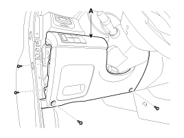
Remove the crash pad lower panel (A).
(Refer to BD group - "Crash pad")
Disconnect the negative (-) battery terminal.
Remove the crash pad lower panel (A).
(Refer to BD group - "Crash pad")

Remove IPM(Intelligent intergrated Platform Module) connector (A), bolts and nut
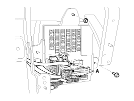
Remove IPM (A) after removing rear connectors.
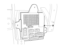
Install IPM(Intelligent intergrated Platform Module).
Connect the IPM connector.
Install the crash pad lower panel.
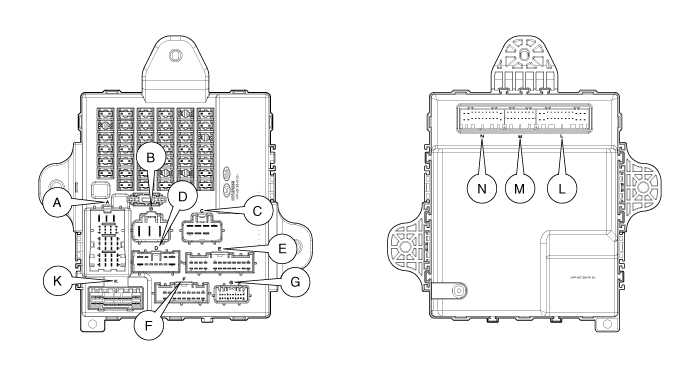
CON. | PIN | Description | Active | Remark |
L | 1 |
|
|
|
2 |
|
|
| |
3 |
|
|
| |
4 | Wiper Intermittent Volume | AD |
| |
5 | Key Illumination Lamp Output |
|
| |
6 | Rear Left Seatwarmer Switch Input |
|
| |
7 | Rear Washer Switch Input | High |
| |
8 |
|
|
| |
9 | Auto Light Switch Input | Low |
| |
10 | Head Lamp Low Switch Input | Low |
| |
11 | Wiper Mist Switch Input | High |
| |
12 | Auto Light Sensor Input | AD |
| |
13 | Auto Light Sensor Ground | Ground |
| |
14 |
|
|
| |
15 | Washer Switch Input | High |
| |
16 |
|
|
| |
17 | Defroster Switch Input | Low |
| |
18 | Rear Right Seatwarmer Switch Input |
|
| |
19 | Wiper Intermittent Switch Input | High |
| |
20 |
|
|
| |
21 | Tail Lamp Switch Input | Low |
| |
22 | Rear Left Seatwarmer Relay Output |
|
| |
23 | Rear Wiper Switch Input | High |
| |
24 | Rear Right Seatwarmer Relay Output |
|
| |
25 | ALS Power Monitoring Input | High |
| |
26 |
|
|
| |
M | 1 | Head |
|
|
2 | Driver Door Unlock Relay Output | Low | Relay | |
3 |
|
|
| |
4 | Rear Fog Relay Output | Low | Relay | |
5 | Can Network Communication Line(high) | Data |
| |
6 | Can Network Communication Line(Low) | Data |
| |
7 |
|
|
| |
8 | Key In Switch Input | Low |
| |
9 | Head Lamp Washer Switch Input | Low |
| |
10 |
|
|
| |
11 |
|
|
| |
12 | Parking Brake Indicator | Low |
| |
13 | Hid Option Switch Input | Low |
| |
14 | Rear Fog Lamp Switch Input | Low |
| |
15 |
|
|
| |
16 | Head Lamp high Switch Input | Low |
| |
N | 1 | Room Lamp Output | Low | PWM |
2 |
|
|
| |
3 | Head Lamp Washer Realy Output | Low | Relay | |
4 |
|
|
| |
5 | Hazard Relay Output | Low | Relay | |
6 |
|
|
| |
7 | AV Tail Signal Output | Low |
| |
8 |
|
|
| |
9 |
|
|
| |
10 | Key Solenoid Output | Low | Solenoid | |
11 | Supply Power To Ips For Mhlld |
|
| |
12 | Power Ground2 | Ground |
| |
13 | Front Fog Lamp Switch Input | Low |
| |
14 | Tx Door Unlock State Signal Output | High |
| |
15 | Assist Seat Belt Indicator Output | Low | LED | |
16 | P Position Switch Input | Low |
| |
17 | Diagnostic Comm. Line K For Tester | Data |
| |
18 | Crash Unlock Signal Input | Low |
| |
19 | Buzzer Output | Low |
| |
20 |
|
|
| |
21 | Manual HLLD Power Output | High |
| |
22 | Power Ground1 | Low | Lamp | |
K | 1 |
|
|
|
2 | Stop Lamp LH/RH Output | High |
| |
3 | Stop Lamp Power | Power |
| |
4 | Power Window Lock Switch Input | Low |
| |
5 | Rear Right Door Open Switch Input | Low |
| |
6 |
| Low |
| |
7 | Rear Left Door Open Switch Input |
|
| |
8 | Parking Brake Switch Input | Low |
| |
9 | Driver Door Key Unlock Switch Input | Low |
| |
10 | Driver Door Open Switch Input | Low |
| |
11 | Tail Gate Out Side Handle Signal Input | Low |
| |
12 | IMS Relay Output | Low | Relay | |
13 | Rear Door Actuator Unlock Switch Input |
|
| |
14 |
|
|
| |
15 |
|
|
| |
16 |
|
|
| |
17 | Seat Belt Switch Input | Low |
| |
18 | Assist Door Open Switch Input | Low |
| |
19 | Tail Gate Open Switch Input | Low |
| |
20 | Rear Parking Assist System Switch Input | Pulse |
| |
21 | Driver Door Key Lock Switch Input | Low |
| |
22 | Rear Wiper Relay Output | Low | Relay | |
23 | Assist Door Actuator Unlock Switch Input | Low |
| |
24 | Power Window Unlock Switch Input | Low |
| |
25 | Assistant Seat Belt Switch Input | Low |
| |
26 | Driver Door Actuator Unlock Switch Input | Low |
|
CON. | PIN | Description | Active | Remark |
A | 1 | Head Lamp Low RH Output | High | PWM |
2 | Head Lamp High RH Output | High | PWM | |
3 | Power (IPS2 & 3) | Power |
| |
4 | Front Fog Lamp Output | High | PWM | |
5 | Tail Lamp RH Output | High |
| |
6 | Power (IPS1 & 4) | Power |
| |
7 | Tail Lamp LH Output | High |
| |
8 | Head Lamp Low LH Output | High | PWM | |
9 | Power (IPS5 & 6) | Power |
| |
10 | Head Lamp High LH Output | High | PWM | |
11 | Tail Interior Lamp Output | High |
| |
12 | Power (IPS0 & 7) | Power |
| |
B | 1 | Power Window Relay Output | Low | Relay |
2 | Ignition2 Switch Input | High |
| |
3 | Drl Option Switch Input | Low |
| |
4 | Battery Monitoring Input | High |
| |
5 | Accessory Switch Input | High |
| |
6 |
|
|
| |
7 |
|
|
| |
8 | Burglar Alarm Horn Relay Output | Low | Relay | |
9 |
|
|
| |
10 | Ignition1 Monitoring Input | High |
| |
11 |
|
|
| |
12 | Tail Gate Release Relay Output | Low | Relay | |
C | 1 |
|
|
|
2 | Door Unlock Relay Output | Low | Relay | |
3 | Door Lock Relay Output | Low | Relay | |
4 |
|
|
| |
5 |
|
|
| |
6 | Wiper Low Relay Output | Low | Relay | |
7 |
|
|
| |
8 | Defroster Relay Output | Low | Relay | |
9 |
|
|
| |
10 | Hood Open Switch Input | Low |
| |
11 | Diagnostic Comm. Line K For Tester | Data |
| |
12 | Start Inhibit Relay Output | Low | Relay |
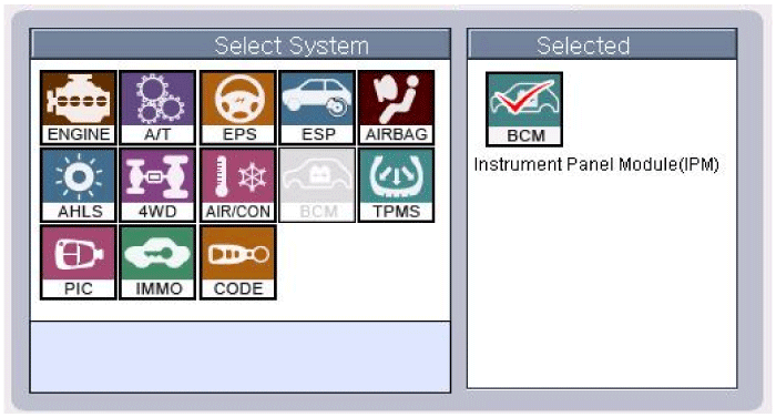
The IPM can be diagnosed by using the GDS. The BCM communicates with the GDS which then displays inputs and outputs along with codes.
To diagnose the IPM function, select the vehicle model and IPM.
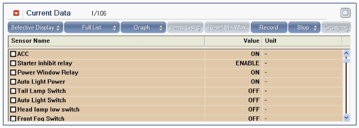
To consult the present input/out value of IPM, "Current DATA". It provides information of IPM input/output conditions of power supply, turn signal/brake lamp, headlamp, door locks, outside mirror, wiper, auto-light and transmitters etc.
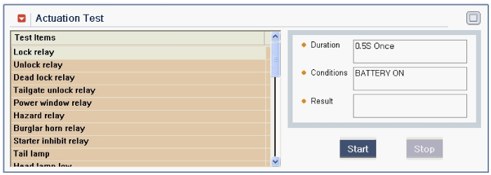
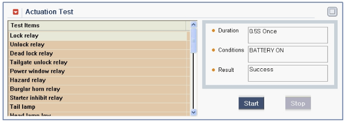
To perform functional test on IPM outputs, select "Actuation Test"
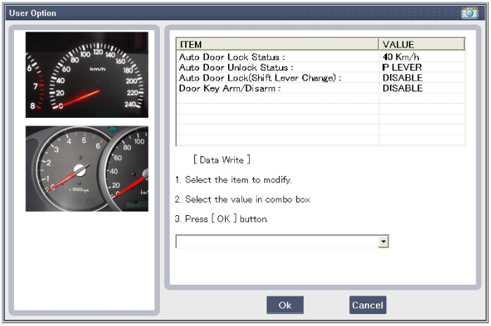
To change the "user option" on BCM, select the "User Option" menu and change the value as below.
