
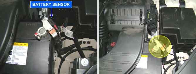
Many control units have applied to vehicle as it becomes more eletrolnical. These units control their own system based on information from diverse sensors. Therefore necessity of common use of diverse sensor information and importance of stable power supply are gathering strength. Battery sensor is mounted on battery (-) terminal. It transmits battery voltage, current, temperature information to PCM. PCM controls generating voltage by duty cycle based on these signals
PCM sets this code when there is difference between battery voltage at power supply terminal of PCM and the voltage from battery senor.
Item | Detecting Condition | Possible cause |
DTC Strategy |
•
Signal Monitoring | 1. Open or short in harness 2. Faulty battery sensor 3. Poor connection |
Enable Conditions |
•
IG "ON". | |
Threshold value |
•
There is difference between battery voltage at power supply terminal of PCM and the voltage from battery senor | |
Diagnosis Time |
•
Continuous | |
MIL On Condition |
•
NO MIL ON (DTC only) |
Fig 1) Normal waveforms of IG, L terminal of alternator during charge warning lamp is ON
Fig 2) Normal waveforms of IG, L terminal of alternator during charge warning lamp is OFF
Fig 3) Normal waveforms of COM, FR terminal of alternator at idle
Fig 4) Normal waveforms of COM, FR terminal of alternator under connector disconnected condition