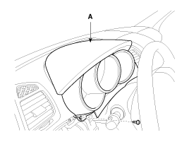
Remove the cluster fascia panel (A).
(Refer to Body - "Crash pad")

Disconnect the negative (-) battery terminal.
Remove the cluster fascia panel (A).
(Refer to Body - "Crash pad")

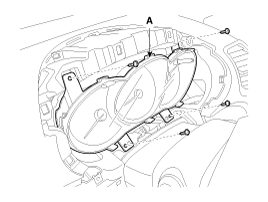
Remove the cluster fascia (A) from the housing after removing 4 screws.

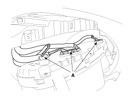
Disconnect the cluster fascia connecters (A) and then remove the cluster.

Connect the cluster connector.
Install the cluster assembly.
Install the cluster facia panel.
Check the suspected area as below table when the warning light is error.
NO | Warning light | Description | Communication | Signal (Unit/Sensor) | Suspected Area |
1 |  | Turn signal -LH | C-CAN | IPM | 1. CAN line faulty |
2 |  | Turn signal -RH | C-CAN | ||
3 |  | Cruise | C-CAN | SCC EMS | 1. CAN line faulty |
4 |  | SET | C-CAN | EMS | 1. CAN line faulty |
5 |  | Front fog | C-CAN | IPM | 1. CAN line faulty |
6 |  | Tail lamp ON | C-CAN | BCM | 1. CAN line faulty |
7 |  | Head lamp low | C-CAN | IPM | 1. CAN line faulty |
8 |  | ECO | Hardwire |
|
|
9 |  | Head lamp high | C-CAN | BCM | 1. CAN line faulty |
10 |  | Seat belt | C-CAN | BCM | 1. CAN line faulty |
11 |  | Air bag | C-CAN | ACU | 1. CAN line faulty |
12 |  | Oil pressure | Hardwire | Oil pressure sensor | 1. Wiring faulty |
13 |  | Oil level | C-CAN | EMS | 1. CAN line faulty |
14 |  | Battery charge | Hardwire (Digital) | Battery sensor | 1. Wiring faulty |
15 |  | Parking brake | C-CAN | IPM ABS | 1. CAN line faulty |
16 |  | Door open | C-CAN | BCM | 1. CAN line faulty |
17 |  | Water separator | Hardwire | Fuel water separator sensor | 1. Wiring faulty |
18 |  | Key out | C-CAN | SMK | 1. CAN line faulty |
19 |  | DBC | C-CAN | TCS | 1. CAN line faulty |
20 |  | Check engine light (MIL) | C-CAN | EMS | 1. CAN line faulty |
21 |  | Glow | C-CAN | EMS | 1. CAN line faulty |
22 |  | VDC(ESC) | C-CAN | TCS | 1. CAN line faulty |
23 |  | VDC OFF (ESC OFF) | C-CAN | TCS | 1. CAN line faulty |
24 |  | ABS | C-CAN | ABS TCS | 1. CAN line faulty |
25 |  | Trunk open | C-CAN | IPM | 1. CAN line faulty |
26 |  | Immobilizer | C-CAN Hardwire | SMK | 1. CAN line faulty 2. Wiring faulty |
27 |  | Fuel warning | Hardwire | Fuel sender | 1. Fuel sender faulty 2. Wiring faulty |
28 |  | Washer warning | Hardwire | Washer fluid level sensor | 1. Wiring faulty |
29 |  | TPMS(TREAD) | C-CAN | TPMS | 1. CAN line faulty |
30 |  | 4WD | C-CAN | 4WD | 1. CAN line faulty |
31 |  | 4WD warning | C-CAN | 4WD | 1. CAN line faulty |
32 |  | EPS | C-CAN | MDPS | 1. CAN line faulty |
33 |  | LDWS | C-CAN | LDWS | 1. CAN line faulty |
34 |  | AFLS | C-CAN | AFLS | 1. CAN line faulty |
Check the suspected area as below table when the gauge is error.
NO | Description | Communication | Signal (Unit/Sensor) | Suspected Area |
1 | Speedometer | C-CAN | TCU | 1. CAN line faulty |
3 | Tachometer | C-CAN | EMS | 1. CAN line faulty |
4 | Coolant temperature | C-CAN | EMS | 1. CAN line faulty |
5 | Fuel level | Hardwire | Fuel sender | 1. Fuel sender faulty 2. Wiring faulty |
6 | Shift indicator | C-CAN | TCU | 1. CAN line faulty |
Check the specified value of cluster connector in specified condition.
NO | Description | Input/ Output | Communication | Value | Specified conditions |
A1 | Air bag | Input | Hardwire | 9~16 | IGN Switch ON |
A2 | P output | Output | Hardwire | 6 ~ 15 | IGN ON & shift the lever in P |
A3 | R Output | Output | Hardwire | 6 ~ 15 | IGN ON & shift the lever in R |
A4 | N Output | Output | Hardwire | 6 ~ 15 | IGN ON & shift the lever in N |
A5 | D Output | Output | Hardwire | 6 ~ 15 | IGN ON & shift the lever in D |
A6 | Rheostat Detent | Output | Hardwire | 6 ~ 15 | IGN ON & rheostat up to max position |
A7 | Fuel | Input | Hardwire | ~1.3 | Gauge is FULL |
7.68~ | Gauge is EMPTY | ||||
A8 | - |
|
|
|
|
A9 | Water separator sensor | Input | Hardwire | ~ 2.7 | IGN switch ON, Warning lamp turn OFF |
A10 | - |
|
|
|
|
A11 | Washer fluid | Input | Hardwire | ~ 2.7 | IGN ON & warning lamp turn ON |
A12 | Rheostat up switch | Input | Hardwire | ~ 2.7 | IGN switch ON, Illumination UP |
A13 | Rheostat down switch | Input | Hardwire | ~ 2.7 | IGN switch ON, Illumination DOWN |
A14 | Heated steering wheel | Input | Hardwire | 5 ~ | Heated steering wheel switch ON |
A15 | Analog switch 1 | Input | Hardwire | Analog switch input power | IGN switch ON & control the analog switch |
A16 | Active ECO | Input | Hardwire | ~ 2.7 | IGN switch ON, ACTIVE ECO switch ON, warning lamp ON |
A17 | Oil pressure | Input | Hardwire | ~ 2.7 | IGN switch ON, warning lamp ON |
A18 | Alternator | Input | Hardwire | ~ 2.7 | IGN switch ON, warning lamp ON |
A19 | Oil level | Input | Hardwire | ~ 2.7 | IGN switch ON, warning lamp ON |
A20 | Immobilizer | Input | Hardwire | ~ 1 | IGN switch ON, warning lamp ON |
A21 | Battery | Input | Hardwire | 9~16 | Always |
A22 | IGN1 | Input | Hardwire | 9~16 | IGN switch ON |
A23 | ILL+ | Input | Hardwire | 9~16 | Tail lamp switch ON |
A24 | Analog switch 2 | Input | Hardwire | Analog switch input power | IGN switch ON & control the analog switch |
A25 | Switch GND | Input | Hardwire | ~1V | Always |
A26 | Signal GND | Input | Hardwire | ~1V | Always |
A27 | Fuel GND | Input | Hardwire | ~1V | Always |
A28 | Fuel warning | Output | Hardwire | ~1.2V | IGN switch ON, warning lamp ON |
A29 | - |
|
|
|
|
A30 | - |
|
|
|
|
A31 | 4P_OUT | Output | Hardwire | ~1.2V | IGN switch ON, vehicle speed over 1KM/H |
A32 | - |
|
|
|
|
A33 | C CAN high | Input | Hardwire | - |
|
A34 | C CAN low | Input | Hardwire | - |
|
A35 | - |
|
|
|
|
A36 | MM CAN high | Input | Hardwire | - |
|
A37 | MM CAN low | Input | Hardwire | - |
|
A38 | - |
|
|
|
|
A39 | Illumination | Output | Hardwire | ~1.5V | IGN ON & tail lamp turn ON |
A40 | Illumination GND | Input | Hardwire | ~1V | Always |
Communication information with another units.
Transmission | Reception | Communication | Remarks |
Cluster | BCM | C-CAN | Fuel supply signal Instantaneous fuel consumption LFW lamp ON signal Vehicle setting Illumination setting |
Cluster | EMS | C-CAN | Active ECO mode |
Cluster | MDPS | C-CAN | Flex steering switch |
Cluster | ACU | C-CAN | Air bag |
ACU | Cluster | CAN | Air bag warning control |
AFLS | Cluster | CAN | AFLS warning lamp |
BCM | Cluster | CAN | Hood warning |
DATC | Cluster | CAN | Outside temperature |
EHPS | Cluster | CAN | Warning message control |
EMS | Cluster | CAN | Tachometer control Temperature gauge control Engine warning simbol, CRUISE, SET warning control |
ESC | Cluster | CAN |
|
BCM | Cluster | CAN | Vehicle setting control Warning and buzzer indicate, PAS control |
LCA | Cluster | CAN | BSD warning message indicate |
LDWS | Cluster | CAN | LDWS warning lamp, message indicate HBA(High Beam Assist) warning lamp control |
SAS | Cluster | CAN | Steering angle indicate |
SMK | Cluster | CAN | Smart key indicate |
TCS | Cluster | CAN | ESC OFF switch information SCC control the brake lamp and indicate |
TCU | Cluster | CAN | Shift lever information (AT) |
TPMS | Cluster | CAN | TPMS information |
The other information about the cluster
USM (User Setting Mode)
USM is set using the steering wheel remote control button.
IMS seat, IMS steering, auto door lock/unlock, head lamp escort, welcome light, welcome sound and triple turn signal lamp are controled.
USM setting procedure
Send the USM value to the BCM
BCM send the setting value to the each module through CAN.
Each modules send the setting complete value to BCM.
BCM send the final setting value to cluster through CAN.